
Core switching and sealing system of valve

A sealing system and switch technology, applied in shaft seal, valve details, valve device, etc., can solve the problems of increased manufacturing cost, reduced service life of valve, plastic gasket and valve stem, etc., so as to achieve low production cost and low production cost The effect of cost increase and simple structure design

Active Publication Date: 2009-12-02
河南熊川流体工程有限公司
View PDF0 Cites 1 Cited by
  • Summary
  • Abstract
  • Description
  • Claims
  • Application Information

AI Technical Summary

Problems solved by technology

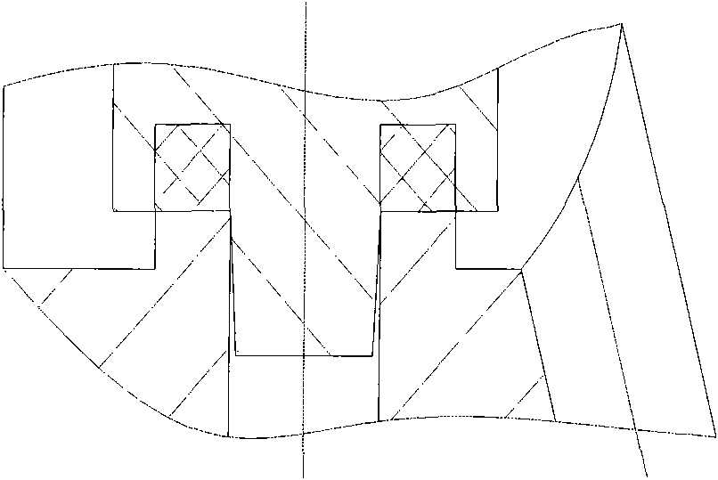
However, there is a problem with this sealing design method: After the globe valve is switched on and off for a period of time, due to the plastic material of the plastic gasket flowing into the gap, the plastic gasket may be separated from the valve stem when the valve needs to be opened, resulting in Problems with seal failure, such as Figure 5 to Figure 8 shown
[0006] Although the above-mentioned solutions have solved the problem of the plastic gasket being separated from the valve stem to a certain extent when the valve needs to be opened, they cannot fundamentally eliminate the assembly gap, and still leave a cold flow space for the plastic gasket, resulting in plastic When the gasket is stressed, cold flow will be generated, which will weaken the sealing effect; if it is used for a long time, especially when working in an alternating temperature environment with a difference between high and low temperature exceeding 50 degrees Celsius, the deformation caused by cold flow will be more severe, and the weakening of the sealing force will be More significantly, thus greatly reducing the service life of the valve
Moreover, due to the complex structure of these methods, the manufacturing cost increases, which directly affects the popularization of products.

Method used


Image

  • Core switching and sealing system of valve
  • Core switching and sealing system of valve
  • Core switching and sealing system of valve

Examples


Embodiment 1

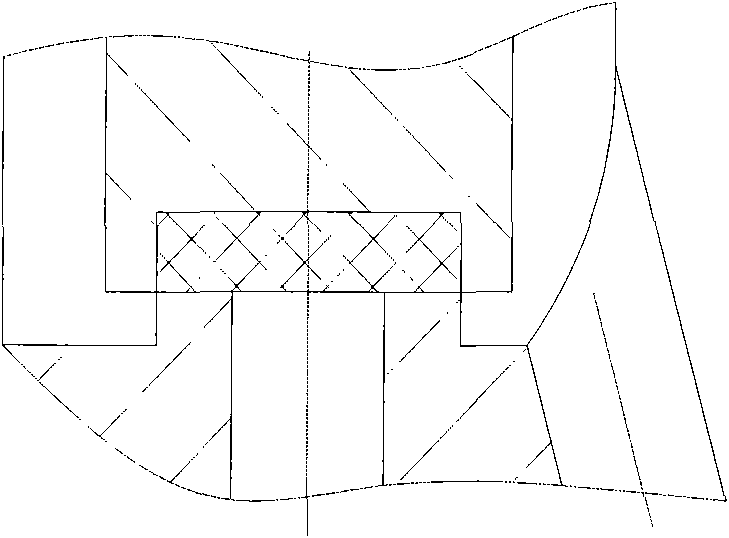
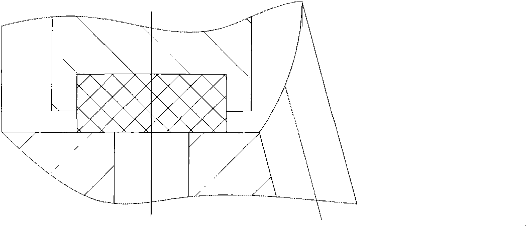
[0043] Embodiment 1 of the present invention provides a core switch sealing system of a valve. The core sealing systems of other valves besides stop valves, such as solenoid valves, toggle switch valves, safety valves, back pressure valves, pressure stabilizing valves, etc. Within the protection scope of the present invention, this embodiment 1 takes a shut-off valve as an example to describe the sealing system. The system specifically includes: a valve stem with an annular groove and a plastic gasket with the same volume as the annular groove sheet;

[0044] The cavity of the annular groove is larger and the opening is smaller, which is used to completely clamp the plastic gasket in the annular groove;

[0045] The thickness of the plastic gasket is equal to the depth of the annular groove, and is used in conjunction with the annular groove to complete the sealing of the shut-off valve.

[0046] Among them, because the volume of the plastic gasket and the annular groove are equal...

Embodiment 2

[0049]Embodiment 2 of the present invention provides a valve sealing system. The core sealing systems of valves other than stop valves, such as solenoid valves, toggle switch valves, safety valves, back pressure valves, and pressure stabilizing valves, are all in this Within the protection scope of the invention, the present embodiment 2 takes a stop valve as an example to describe the sealing system. See Picture 12 The sealing system specifically includes: a valve stem 121 with an annular groove and a plastic gasket 122; wherein the volume of the annular groove on the valve stem 121 is equal to that of the plastic gasket 122, and the depth of the annular groove is equal to that of the plastic gasket. The thickness is equal. Among them, the cavity of the annular groove is larger and the opening is smaller, and the plastic gasket cooperates with the annular groove to complete the sealing function.

[0050] See Figure 13 The outer side wall surface of the annular groove of the val...


PUM

PropertyMeasurementUnit
Half cone angleaaaaaaaaaa

Abstract

The invention discloses a core switching and sealing system of a valve and belongs to the field of core sealing. The system comprises a valve rod with an annular groove and a plastic gasket in the same volume as the annular groove, wherein the annular groove has a large cavity and a small opening and is used for completely clamping the plastic gasket in the annular groove; and the thickness of the plastic gasket and the depth of the annular groove are equal, and the plastic gasket is used together with the annular groove to complete the sealing of the valve. The annular groove is designed with the shape with the large cavity and the small opening for completely clamping the plastic gasket in the annular groove, the volume of the annular groove is equal to that of the plastic gasket and the thickness of the plastic gasket is equal to the depth of the annular groove, so that the plastic material has no space for cold flows and the valve sealing is reliable even in alternating temperature environments are guaranteed effectively; and at the same time, the plastic gasket cannot separate from the valve rode due to the clamping action of the annular groove.

Description

Technical field [0001] The invention relates to the field of core sealing, in particular to a core switch sealing system of a valve. Background technique [0002] "Valve" is a device used to control the direction, pressure, and flow of fluid in a fluid system. The valve is a control component in the pipeline fluid conveying system. It is used to change the section of the passage and the direction of the medium flow. It has the functions of diversion, cutoff, adjustment, throttling, check, diversion or overflow pressure relief. Valves used for fluid control, from the simplest shut-off valve to various valves used in extremely complex automatic control systems, have a wide variety and specifications. The most important part of the valve is the sealing system directly related to the open and closed states, because once the core switch sealing system of the valve fails, the fluid cannot be completely shut off, resulting in waste of resources and loss of public property. [0003] Take...

Claims


Application Information

Patent Timeline
IPC IPC(8): F16K41/02
Inventor 刘茯蔚
Owner 河南熊川流体工程有限公司
Learn More