
Micromechanical tuning fork gyroscope

A tuning fork gyro and micro-mechanical technology, applied in the field of inertial devices, can solve the problems of reducing the measurement accuracy of micro-mechanical gyroscopes, and achieve the effect of compact structure and small size

Inactive Publication Date: 2009-12-02
UNIV OF ELECTRONIC SCI & TECH OF CHINA
View PDF0 Cites 6 Cited by
  • Summary
  • Abstract
  • Description
  • Claims
  • Application Information

AI Technical Summary

Problems solved by technology

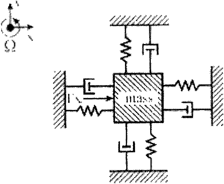
[0012] Therefore, the displacement of the mass block measured by the detection capacitance not only includes the effect of Coriolis acceleration, but also includes the driving signal F x The error component on the Y axis, in this case, if you still use the formula (2) to calculate the Coriolis acceleration a, and further obtain the input angular velocity Ω, there must be an error component F xy Influencing factors, thereby reducing the measurement accuracy of the micromachined gyroscope

Method used


Image

  • Micromechanical tuning fork gyroscope
  • Micromechanical tuning fork gyroscope
  • Micromechanical tuning fork gyroscope

Examples


Embodiment Construction

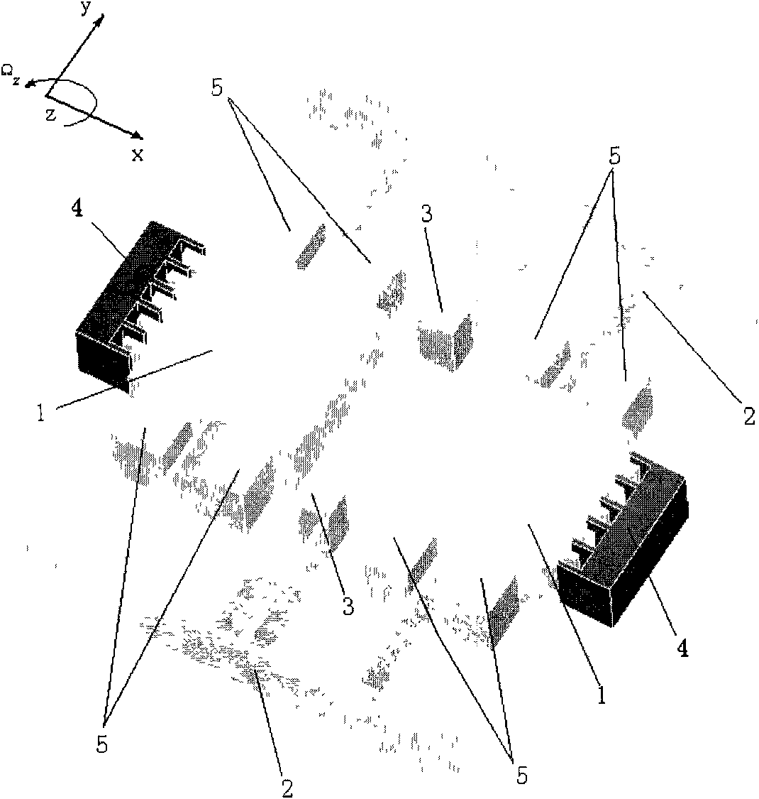
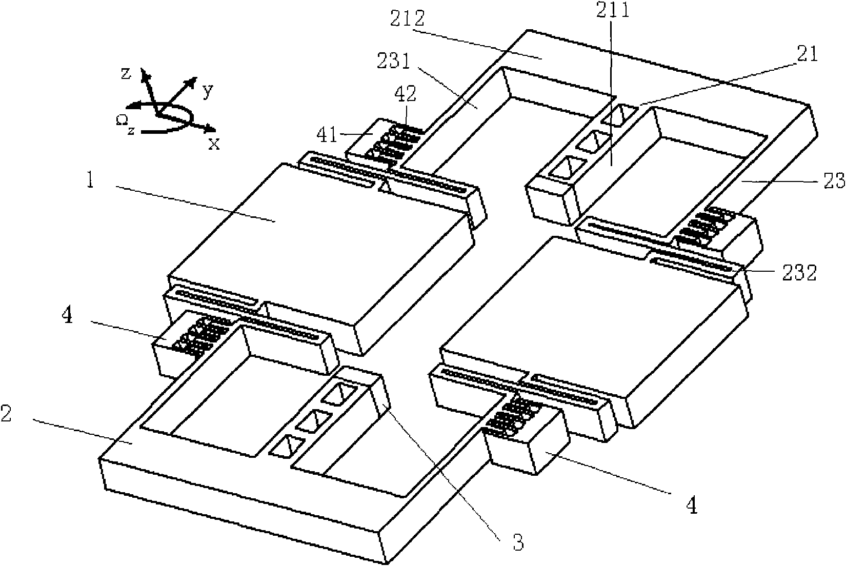
[0027] A micromachined tuning fork gyro, comprising a micromachined tuning fork gyro structure, such as image 3 As shown, the micromechanical tuning fork gyro structure includes two mass blocks 1 , two tuning fork folded cantilever beams 2 , two pillars 3 , and four driving comb teeth 4 . The tuning fork folding cantilever beam 2 is a tuning fork structure, which is composed of a "T"-shaped connecting beam 21 and two folding beams 23; wherein: the "T"-shaped connecting beam 21 is composed of a longitudinal beam 211 and a cross beam 212; Two ends of the beam 212 of the "T"-shaped connecting beam 21 are respectively connected to a folded beam 23; the folded beam 23 includes a straight section 231 and a folded section 232. The first mass block 1 is connected between the folded portion 232 of the first folded beam 23 of the first tuning fork folded cantilever beam 2 and the folded portion 232 of the first folded beam 23 of the second tuning fork folded cantilever beam 2; The sec...


PUM


Abstract

The invention provides a micromechanical tuning fork gyroscope, belongs to the technical field of inertia devices, and relates to a micromechanical gyroscope for measuring a spacial angle position of an object. The micromechanical tuning fork gyroscope comprises two mass blocks, two tuning fork folding cantilevers, two posts and four driving combs; each tuning fork folding cantilever consists of a T-shaped connecting beam and two folding beams; each folding beam comprises a linear part connected with the connecting beam and a folding part connected with the mass blocks; the mass blocks and the tuning fork folding cantilevers are supported on a base through the posts, so that the whole micromechanical tuning fork gyroscope structure is parallelly suspended above the base; and movable comb electrodes of the driving combs are fixed on linear parts of the tuning fork folding cantilevers and close to lateral surfaces of folding parts of the tuning fork folding cantilevers. The micromechanical tuning fork gyroscope has high Q value and mechanical rigidity coupling characteristic between a low driving mode and a detection mode, and simultaneously can improve the measuring accuracy of the micromechanical tuning fork gyroscope, so that the micromechanical tuning fork gyroscope can be applied in the fields with inertia levels under harsher conditions.

Description

technical field [0001] The invention belongs to the technical field of inertial devices, and relates to a micromechanical gyroscope for measuring the angular position of an object in space. Background technique [0002] Gyroscopes have a history of more than 100 years of development since 1910, when humans first produced compass for shipboard compass. Its development process can be roughly divided into four stages: the first stage is the ball bearing supporting gyro motor or frame gyroscope; the second stage is the liquid floating or air floating gyroscope developed from the late 1940s to the early 1950s. The third stage is the rotor gyroscope with dry dynamic flexible support developed after the 1960s; the development of gyroscopes has entered the fourth stage, namely electrostatic gyroscopes, laser gyroscopes, and fiber optic gyroscopes. instruments and micromachined gyroscopes. The micromechanical gyroscope is a kind of technology that uses solid materials, especially s...

Claims


Application Information

Patent Timeline
IPC IPC(8): G01C19/56B81B7/02G01C19/5621
Inventor 刘晓明管继平
Owner UNIV OF ELECTRONIC SCI & TECH OF CHINA
Learn More