
Doped region forming method

A technology of doping regions and doping regions, which is applied in the field of doping region formation, can solve the problems of increasing in-situ doping steps of dopants, complex operation, etc., and achieve the effect of reducing doping loss and surface depression

Active Publication Date: 2012-05-16
SEMICONDUCTOR MANUFACTURING INTERNATIONAL (BEIJING) CORP
View PDF6 Cites 0 Cited by
  • Summary
  • Abstract
  • Description
  • Claims
  • Application Information

AI Technical Summary

Problems solved by technology

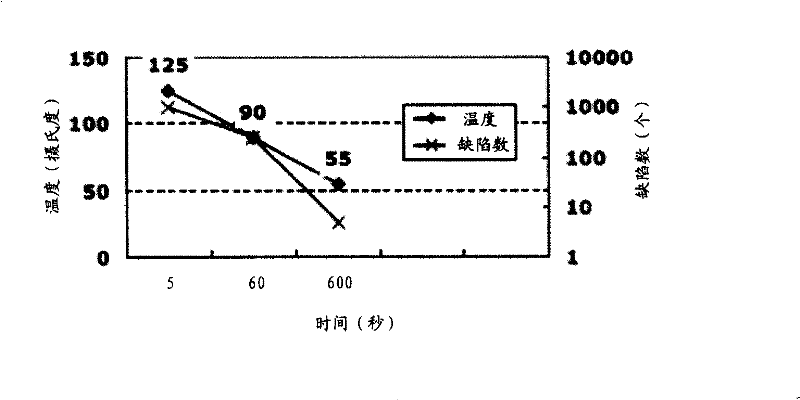
That is, when using the above method to manufacture semiconductor elements, in order to reduce the doping loss, it is necessary to increase the in-situ doping step of the dopant, and the operation is complicated.

Method used


Image

  • Doped region forming method
  • Doped region forming method
  • Doped region forming method

Examples


Embodiment Construction

[0020] Although the invention will be described in more detail below with reference to the accompanying drawings, in which preferred embodiments of the invention are shown, it should be understood that those skilled in the art can modify the invention described herein and still achieve the advantageous effects of the invention. Therefore, the following description should be understood as a broad instruction for those skilled in the art, rather than as a limitation of the present invention.

[0021] In the interest of clarity, not all features of an actual implementation are described. In the following description, well-known functions and constructions are not described in detail since they would obscure the invention with unnecessary detail. It should be appreciated that in the development of any actual embodiment, numerous implementation details must be worked out to achieve the developer's specific goals, such as changing from one embodiment to another in accordance with sy...


PUM


Abstract

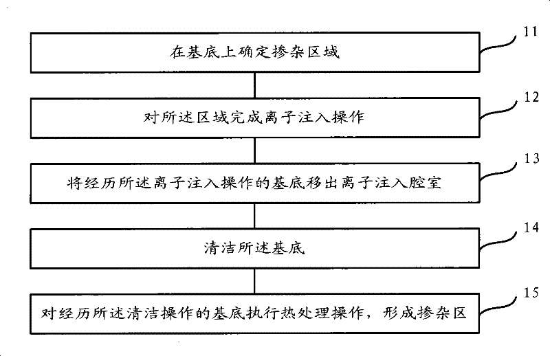
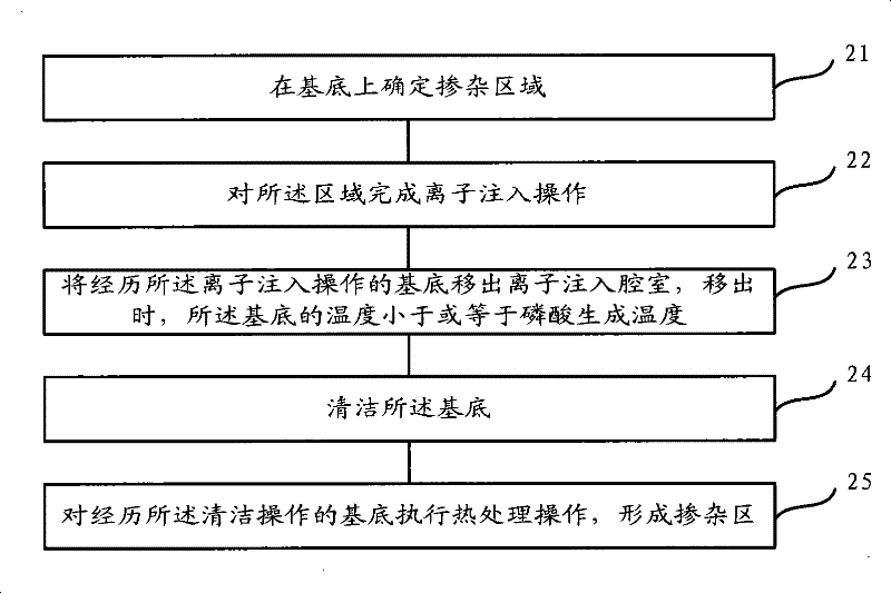
The invention relates to a doped region forming method, comprising the following steps: determining a doped region on a substrate; operating ion implantation on the region; injecting ion reomoved from the substrate, which goes through the ion implantation into an chamber; when the ions are removed, temperature of the substrate is less than or equal to the phosphoric acid generating temperature; cleaning the substrate; operating heat treatment process on the substrate which goes through the cleaning operation to form the doped region. The surface indentation of the doped region can be reduced,thus reducing the doping loss.

Description

technical field [0001] The invention relates to the technical field of semiconductor manufacturing, in particular to a method for forming a doped region. Background technique [0002] The doped region includes a well region, a lightly doped region and a heavily doped region. The well region is used to adjust the threshold voltage of the device and avoid common problems of the device, such as latch-up effect and the like. The lightly doped region includes a lightly doped drain implantation (Lightly Doped Drain, LDD) region and a pocket (Pocket) ion implantation region, and the lightly doped region is used to define a source-drain extension region of the MOS device. The LDD impurity is located below the gate and close to the edge of the channel region, and the Pocket impurity is located below the LDD region and close to the edge of the channel region, both of which provide impurity concentration gradients for the source / drain regions. The heavily doped region includes source...

Claims


Application Information

Patent Timeline
Patent Type & Authority Patents(China)
IPC IPC(8): H01L21/04
Inventor 韩秋华杜珊珊韩宝东李泽逵
Owner SEMICONDUCTOR MANUFACTURING INTERNATIONAL (BEIJING) CORP
Learn More