Metal grid forming method

A metal gate, metal layer technology, applied in electrical components, semiconductor/solid-state device manufacturing, semiconductor devices, etc., can solve problems such as difficulty in controlling the etching selectivity ratio and damage to the substrate surface of metal gates

Inactive Publication Date: 2009-12-02
SEMICONDUCTOR MANUFACTURING INTERNATIONAL (BEIJING) CORP
View PDF1 Cites 30 Cited by
  • Summary
  • Abstract
  • Description
  • Claims
  • Application Information

AI Technical Summary

Problems solved by technology

[0004] In practice, when removing the patterned polysilicon layer, a dry etching process is usually used, resulting in that even if a gate dielectric layer is sandwiched between the polysilicon layer and the substrate, since the gate dielectric layer is thin and difficult to control The etch selectivity ratio between the polysilicon layer, the gate dielectric layer and the substrate, the plasma involved in the dry etching process causes the metal gate to bear during the process of removing the patterned polysilicon layer basal surface damage

Method used


Image

  • Metal grid forming method
  • Metal grid forming method
  • Metal grid forming method

Examples


Embodiment Construction

[0040] Although the invention will be described in more detail below with reference to the accompanying drawings, in which preferred embodiments of the invention are shown, it should be understood that those skilled in the art can modify the invention described herein and still achieve the advantageous effects of the invention. Therefore, the following description should be understood as a broad instruction for those skilled in the art, rather than as a limitation of the present invention.

[0041] In the interest of clarity, not all features of an actual implementation are described. In the following description, well-known functions and constructions are not described in detail since they would obscure the invention with unnecessary detail. It should be appreciated that in the development of any actual embodiment, numerous implementation details must be worked out to achieve the developer's specific goals, such as changing from one embodiment to another in accordance with sy...


PUM


Abstract

The invention relates to a metal grid forming method, comprising the following steps: forming a gate dielectric layer on a substrate; forming an imaging amorphous carbon layer on the gate dielectric layer; forming a side wall surrounding the imaging amorphous carbon layer; forming a interlevel dielectric layer coating the imaging amorphous carbon layer and the side wall; flattening the interlevel dielectric layer and exposing the imaging amorphous carbon layer; removing the imaging amorphous carbon layer by oxygen ashing process to form grooves in the interlevel dielectric layer; forming metal layers to fill the grooves and coat the interlevel dielectric layer. The invention also provides another metal grid forming method. The surface damage of the substrate supporting the metal grid can be reduced by both of the methods.

Description

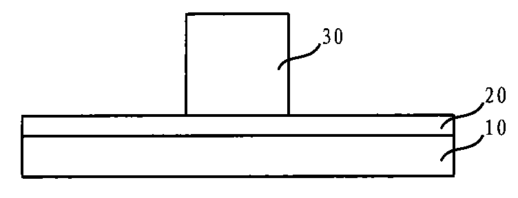
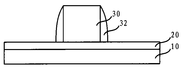
technical field [0001] The invention relates to the technical field of semiconductor manufacturing, in particular to a method for forming a metal gate. Background technique [0002] As the process node shrinks to 45nm and below, metal gates are widely used in order to meet new requirements caused by device size reduction. [0003] As involved in the Chinese patent with the announcement number "CN 100364058C" published on January 23, 2008, generally, the steps of forming a metal gate include, step 101: as figure 1 As shown, a gate dielectric layer 20 is formed on the substrate 10; step 102: as figure 2 As shown, a patterned polysilicon layer 30 is formed on the gate dielectric layer 20; step 103: as image 3 As shown, forming sidewalls 32 surrounding the patterned polysilicon layer 30; step 104: as Figure 4 As shown, an interlayer dielectric layer 40 covering the patterned polysilicon layer 30 and sidewalls 32 is formed; step 105: as shown in 5, planarize the interlayer ...

Claims


Application Information

Patent Timeline
Patent Type & Authority Applications(China)
IPC IPC(8): H01L21/28H01L21/336
Inventor 郑春生杨瑞鹏
Owner SEMICONDUCTOR MANUFACTURING INTERNATIONAL (BEIJING) CORP
Why Eureka
Try Eureka