Wound rotor self-starting permasyn motor

A permanent magnet synchronous, wound rotor technology, applied to synchronous motors with stationary armatures and rotating magnets, synchronous machine parts, magnetic circuit rotating parts, etc., can solve the problem of motor starting difficulties, low starting torque, Problems such as poor pull-in synchronization ability, etc., to achieve the effect of improving pull-in synchronization ability, reducing motor slip, and improving starting performance

Inactive Publication Date: 2009-12-02
SHENYANG POLYTECHNIC UNIV
View PDF0 Cites 17 Cited by
  • Summary
  • Abstract
  • Description
  • Claims
  • Application Information

AI Technical Summary

Problems solved by technology

[0002] At present, most heavy-duty starting motors generally use wound induction motors to improve the starting performance of the motor under heavy-duty starting conditions. However, due to the characteristics of the asynchronous motor itself, it is difficult to design multi-stage, so it is difficult to achieve low-speed operation. The balance of power, 90% of the motor must be used with a huge reduction mechanism. After the motor uses a gear reducer, the size of the transmission system increases, the weight increases, the noise is high, the moment of inertia is large, the efficiency is low, and maintenance is difficult. Negative consequences, in addition to the low efficiency and power factor of induction motors at light load operation, which is not conducive to use under load changing conditions
[0003] The permanent magnet motor has the advantages of simple structure, reliable operation, small size, light weight, low loss, and high efficiency. More importantly, it can maintain high efficiency and power factor under variable load operating conditions, which greatly saves electric energy. At the same time, it can be made into multi-stages to achieve low-speed operation, and the reducer is eliminated to achieve direct drive. However, most self-starting permanent magnet synchronous motors usually use the cast aluminum structure of the cage rotor, which has low starting torque, large starting current, and Difficulty, poor pull-in synchronous ability and poor running stability, so in many working conditions, especially when starting with heavy loads, the starting of the motor is more difficult, so the application range of self-starting permanent magnet synchronous motors is limited

Method used


Image

  • Wound rotor self-starting permasyn motor
  • Wound rotor self-starting permasyn motor
  • Wound rotor self-starting permasyn motor

Examples


Embodiment Construction

[0019] The detailed structure of the wound rotor self-starting permanent magnet synchronous motor of the present invention is described in conjunction with the embodiments.

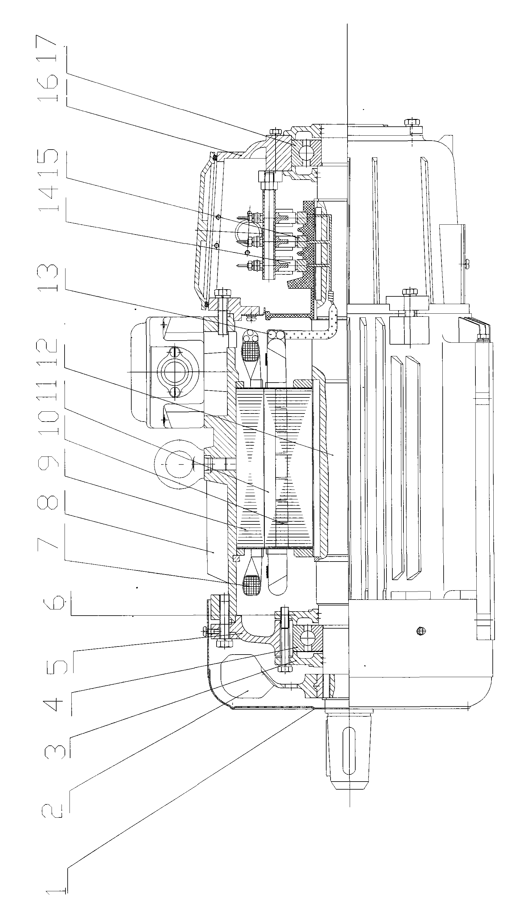
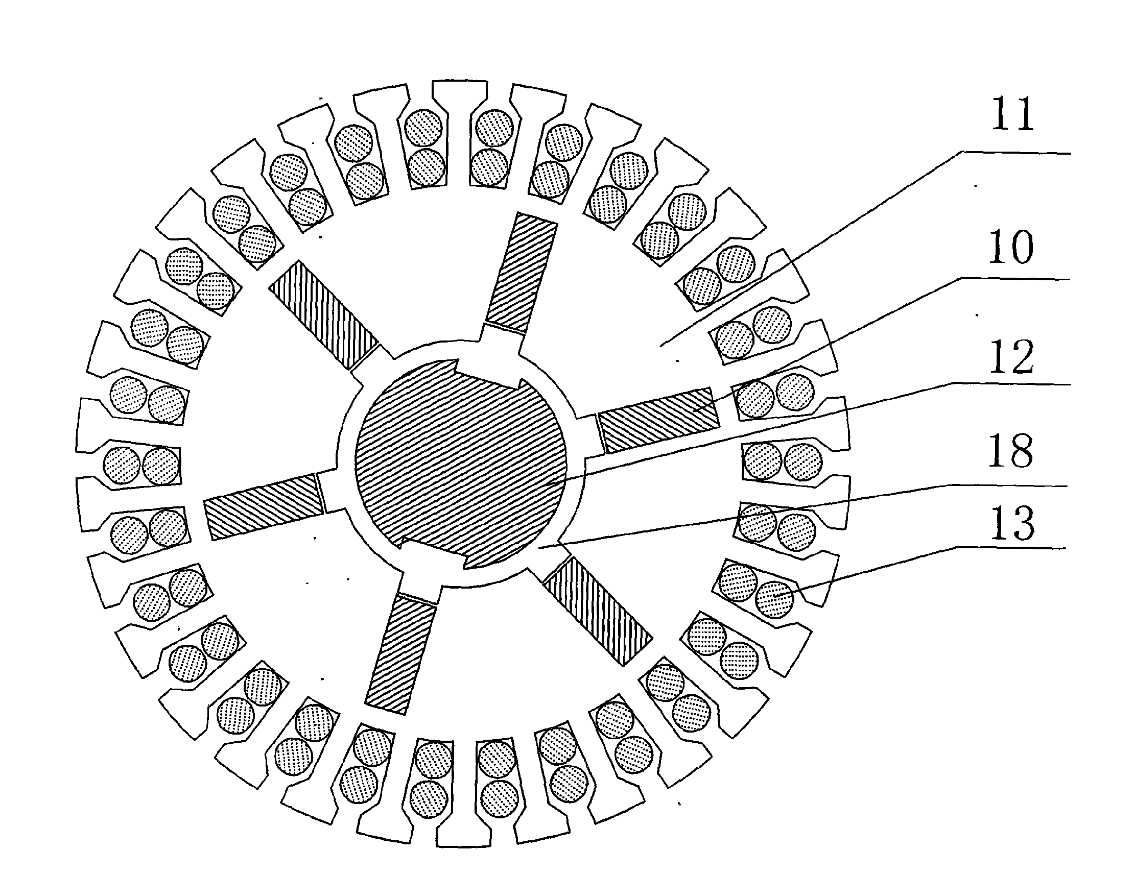
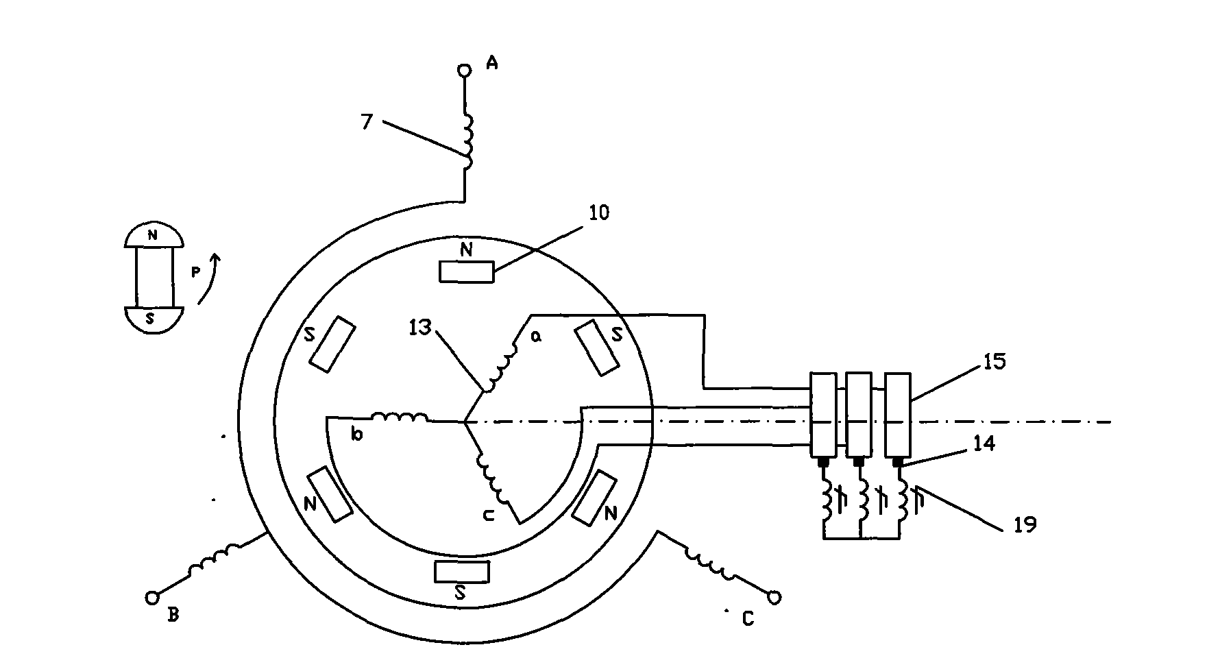
[0020] The device as figure 1 , 2 As shown, it includes fan cover 1, fan 2, bearing front end cover 3, front bearing 4, motor front end cover 5, bearing rear end cover 6, stator winding 7, housing 8, stator core 9, permanent magnet 10, rotor core 11 , rotating shaft 12, rotor winding 13, brush 14, slip ring 15, motor rear end cover 16, rear bearing 17 and magnetic isolation bridge 18.

[0021] The fan 2 of this device is connected with the rotating shaft 12 through the front bearing 4, the fan cover 1 is added on the fan 2, the bearing front end cover 3 and the bearing rear end cover 4 are installed on the front bearing 4, the motor front end cover 5 is above the front bearing 4, and the stator core 9 is fixed on the shell 8, the stator core 9 is provided with a stator slot, and the stator winding 7 is ...


PUM


Abstract

The invention relates to a wound rotor self-starting permasyn motor, which belongs to the technical field of permanent magnet motors. The wound rotor self-starting permasyn motor comprises a fan housing, a fan, a front bearing end cover, a front bearing, a front motor end cover, a rear bearing end cover, a stator winding, a shell, a stator core, a permanent magnet, a rotor core, a rotating shaft, a rotor winding, an electric brush, a slip ring, a rear motor end cover, a rear bearing and a magnetic shielding bridge. The wound rotor self-starting permasyn motor has the following advantages: a wound rotor structure can improve the starting performance of the permasyn motor, namely the starting torque, reduce the starting current, improve the force-energy index, and simultaneously reduce the motor slip ratio by removing the rotor resistance gradually, improve the capability of pulling into synchronism to adapt to the operating condition requirement on low speed and large torque of overload starting, prevent impact to an electric network due to overlarge starting current or the incapability of starting the motor due to undersize starting torque, and ensure the smooth pulling into synchronism of the motor at the same time.

Description

technical field [0001] The invention belongs to the technical field of permanent magnet motors, in particular to a self-starting permanent magnet synchronous motor with wound rotors. Background technique [0002] At present, most heavy-duty starting motors generally use wound induction motors to improve the starting performance of the motor under heavy-duty starting conditions. However, due to the characteristics of the asynchronous motor itself, it is difficult to design multi-stage, so it is difficult to achieve low-speed operation. The balance of power, 90% of the motor must be used with a huge reduction mechanism. After the motor uses a gear reducer, the size of the transmission system increases, the weight increases, the noise is high, the moment of inertia is large, the efficiency is low, and maintenance is difficult. Adverse consequences, in addition, the efficiency and power factor of induction motors are very low when running at light loads, so it is not conducive t...

Claims


Application Information

Patent Timeline
Patent Type & Authority Applications(China)
IPC IPC(8): H02K21/12H02K1/27H02K21/02
Inventor 张炳义冯桂宏
Owner SHENYANG POLYTECHNIC UNIV
Why Eureka
Try Eureka