
Thermal management device and method for making the same

A heat control and heat source technology, applied in chemical instruments and methods, manufacturing tools, lamination devices, etc., can solve problems such as increased difficulty, poor thermal conductivity, high thermal resistance, etc., to reduce manufacturing costs and time, improve thermal performance, Effect of reducing thermal resistance

Active Publication Date: 2014-11-05
THE BOEING CO
View PDF4 Cites 1 Cited by
  • Summary
  • Abstract
  • Description
  • Claims
  • Application Information

AI Technical Summary

Problems solved by technology

[0003] Existing thermal control devices may require the integration of composite materials and multiple interfaces, often with adhesives in between, which have higher thermal resistance and can lead to poor thermal conductivity
Also, known thermal control devices can be relatively expensive to manufacture because more than one process is required to assemble and manufacture the individual parts
These design and constraints imposed by existing manufacturing techniques may limit design flexibility and result in suboptimal performance for some applications
Additionally, the relentless pursuit of higher loop densities and smaller component sizes may complicate the design of more efficient thermal control devices

Method used


Image

  • Thermal management device and method for making the same
  • Thermal management device and method for making the same
  • Thermal management device and method for making the same

Examples


Embodiment Construction

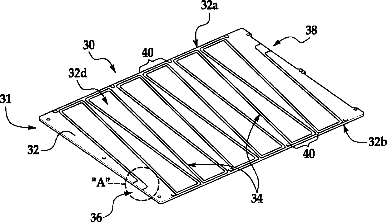
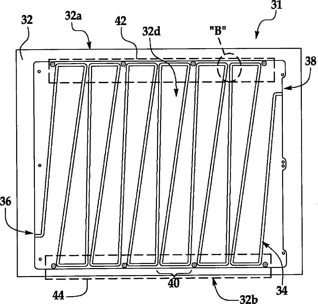
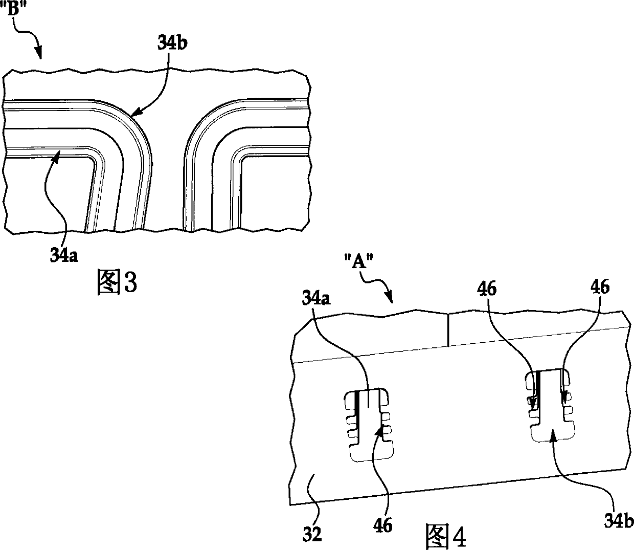
[0077] first reference Figure 1-8 , the disclosed embodiments generally relate to a thermal control device 30 comprising a monolithic (monolithic, monocoque) body 32 having an internal inset channel 34 . exist Figure 1-8 In the depicted embodiment, the monolithic body 32 comprises a generally rectangular plate that, as will be discussed below, can be used as a chassis 32c (see Figure 13 ), the chassis 32c has broad surfaces 32d, 32e on which heat generating elements (not shown) can be mounted. The monolithic body 32 may be formed from a thermally conductive material using a consolidation or similar process to be discussed later, in which successive layers of material are fused to form a monolithic, one-piece body 32 in which the channel 34 is connected to the body 32. Overall shape. By way of example and not limitation, body 32 may comprise an alloy consisting of one or more of aluminum, copper, manganese, nickel, gold, silver, and titanium.

[0078] exist Figure 1-8 ...


PUM


Abstract

A thermal management device suitable for use as an electronic chassis includes a monolithic, monocoque body having integrally formed channels for carrying thermal energy away from a heat source, such as electronic components. The device may be fabricated using additive / subtractive manufacturing processes such as ultrasonic consolidation.

Description

technical field [0001] The present disclosure relates generally to controlling thermal energy generated by a heat generating source, such as an electronic component, and in particular to devices for directing thermal energy away from the heat generating source, and methods of making the same. Background technique [0002] Many devices have been developed for removing heat away from thermal sources such as printed circuit boards (PCBs) to avoid adverse effects on heat sensitive components. In one form of these devices, discrete heat pipes are assembled between separate metal sheets. Heat generated by the electronic components is conducted through the metal sheet to the heat pipe, where the heat is carried away by the flow of heat transfer fluid. Another known device employs a layer of thermally conductive solid material, such as thermally conductive graphite, placed between two discrete sheets of material. Component heat is transferred from the component through the thermal...

Claims


Application Information

Patent Timeline
Patent Type & Authority Patents(China)
IPC IPC(8): H05K7/20B23K20/10
CPCH01L2924/0002H05K7/20545B32B37/00F28F13/00B32B2311/00B32B2310/028F28F3/12F28F21/08F28F7/02F28F1/40F28F3/02H01L2924/00H01L23/36H01L23/34H05K7/20
Inventor T·K·(S·)恩古耶G·L·邓肯B·L·德罗伦D·M·鲍登
Owner THE BOEING CO
Learn More