
Cloth bag frame with dust collecting bag capable of being popped automatically

An automatic pop-up, bag holder technology, applied in suction filters and other directions, can solve the problems of scattering, excessive force of paper bags, shaking, etc., and achieve the effect of high support strength and high-end quality

Inactive Publication Date: 2009-12-09
LG ELECTRONICS (TIANJIN) APPLIANCES CO LTD
View PDF0 Cites 19 Cited by
  • Summary
  • Abstract
  • Description
  • Claims
  • Application Information

AI Technical Summary

Problems solved by technology

[0007] The prior art has the following disadvantages: the dust bag in the prior art is manually inserted or taken out from the bag holder, but when the dust bag is full of dust, some fine dust will gather around it, and the dust will be collected by hand. During the process of removing the bag from the bag holder, it will inevitably come into contact with dust, which will dirty the user's hands; and the paper bag is often shaken due to excessive force during the removal process, and the surrounding dust will be scattered into the dust bag outside of

Method used


Image

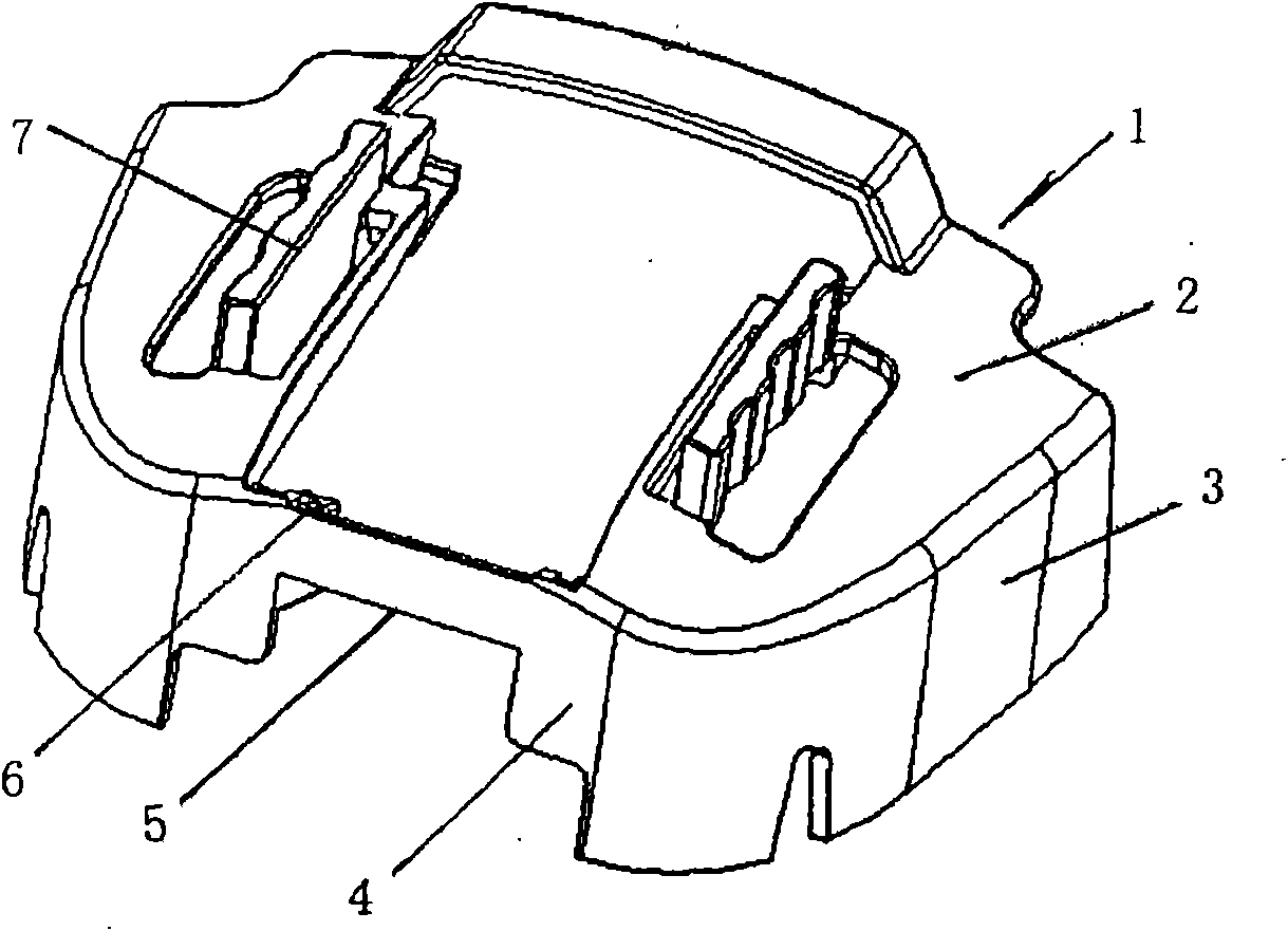
  • Cloth bag frame with dust collecting bag capable of being popped automatically
  • Cloth bag frame with dust collecting bag capable of being popped automatically
  • Cloth bag frame with dust collecting bag capable of being popped automatically

Examples


Embodiment Construction

[0066] The present invention will be described in detail below with reference to the drawings and examples.

[0067] In the drawings of the present invention, the same components as those in the prior art use the same symbols.

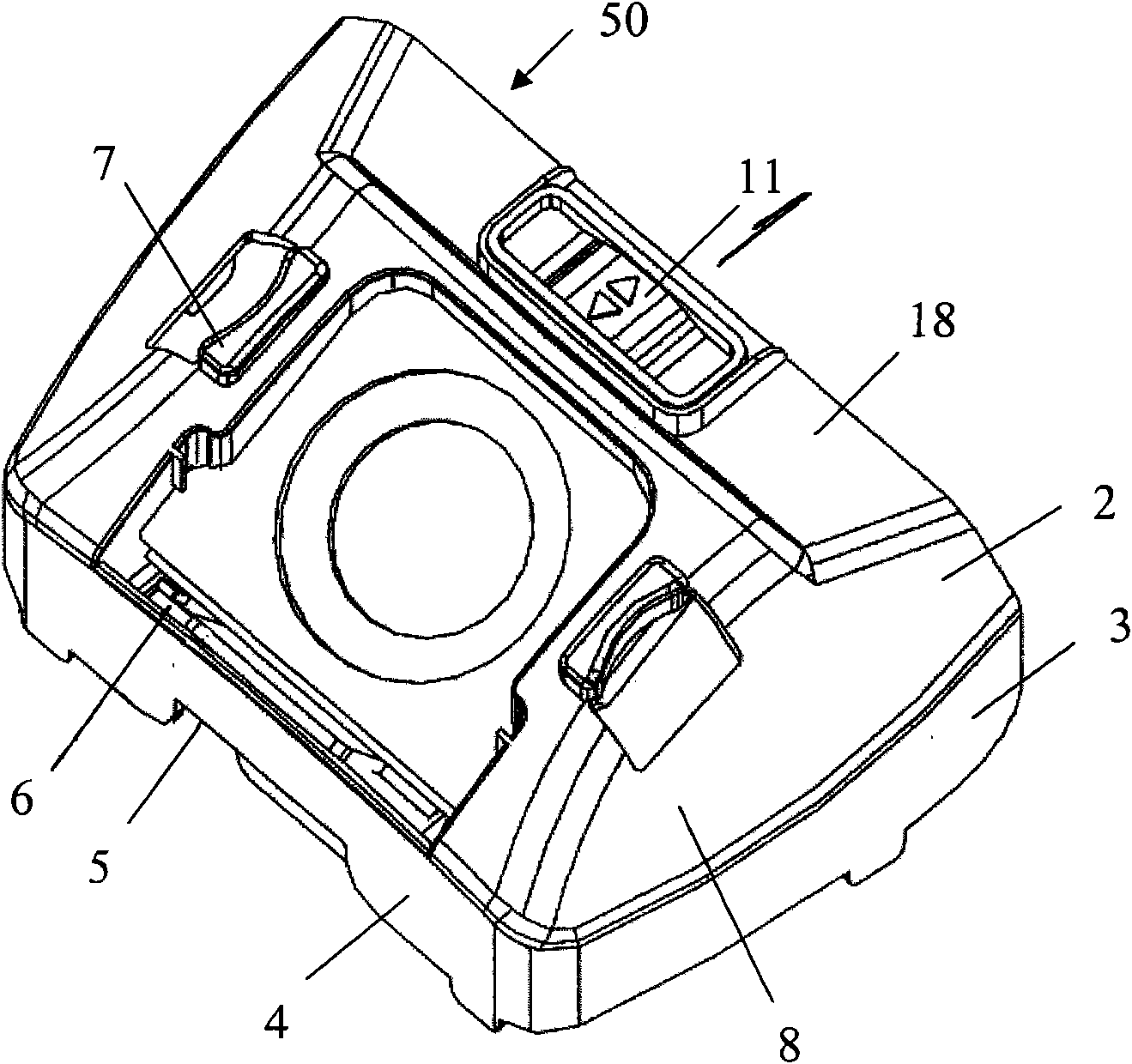
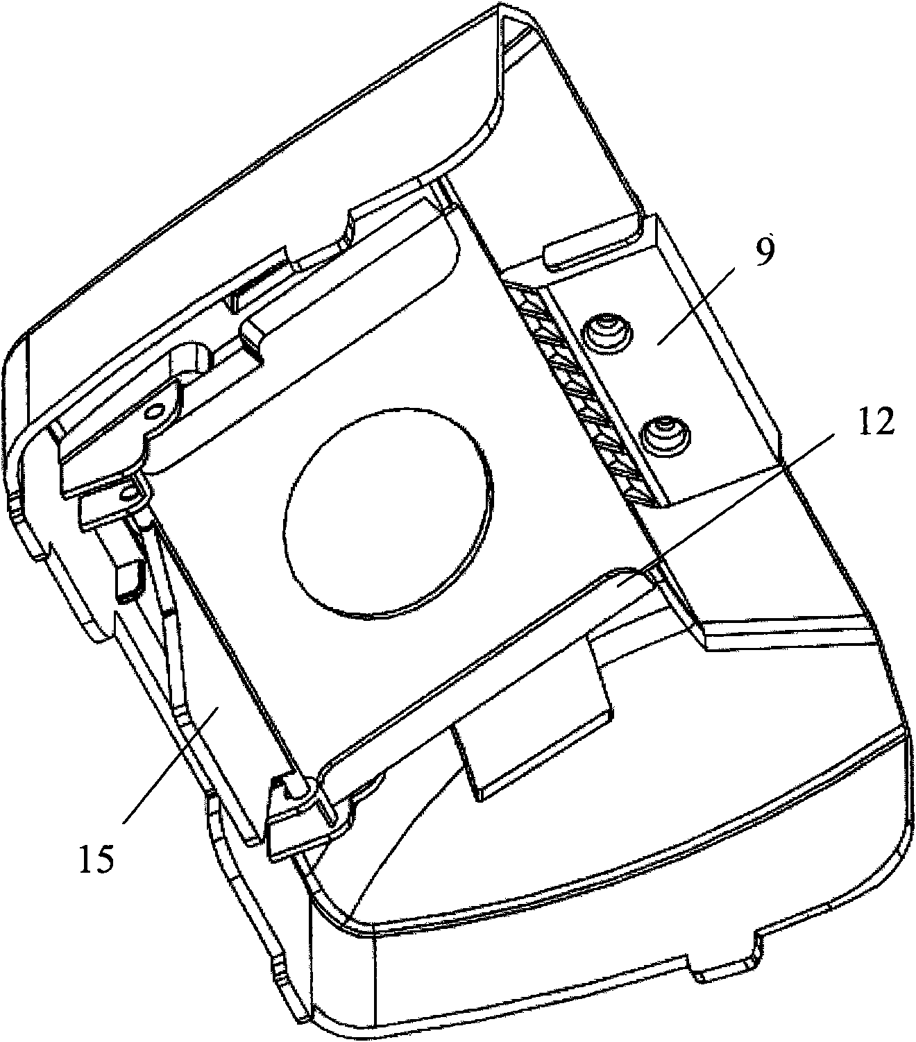
[0068] The cloth bag frame 50 that the dust bag of the present invention pops up automatically, such as figure 2 , image 3 , Figure 4 as shown,

[0069] figure 2 It is a three-dimensional view of the bag frame structure of the present invention; image 3 It is a three-dimensional view of the back structure of the bag rack of the present invention; Figure 4 It is an exploded view of the bag frame structure of the present invention.

[0070] The cloth bag rack 50 that the dust bag of the present invention pops up automatically includes: a side panel 3 extending downwards connected with both sides and the front end of the panel 2, a front panel 4, and a stepped opening 5 on the front panel. On the inner side of the dashboard, a housing 8 consist...


PUM


Abstract

The invention relates to a cloth bag frame with a dust collecting bag capable of being popped automatically, which comprises a shell, a sliding button, a supporting lock, a plug board frame, a plug board, a rotating board and a torsion spring, wherein the shell comprises a panel, side surrounding boards, a front surrounding board, a handle and a bracket arranged at the upper edge of a notch at the inner side of the front surrounding board; the sliding button is connected with the upper surface of the back part of the shell; the supporting lock is connected with the lower surface of the back part of the shell and is internally provided with a compression spring; the plug board frame is arranged in a central mounting hole of the shell; the plug board is inserted into the plug board frame and is provided with a cloth bag; the rotating board is connected with the front part of the inner side of the shell; and the torsion spring is connected with the rotating board. A connection board which is connected with the left side surrounding board and the right side surrounding board is arranged behind the mounting hole in the middle of the shell; two long through holes are formed in the middle of the connection board; a shifting sheet which protrudes downward is arranged at the inner side surface of the shell below the connection board; each of the two sides of the bracket at the inner side of the shell is provided with a supporting axle hole; and each of the two sides at the inner side of the front part of the shell is provided with an axle hole. The invention has the advantages that when the dust collecting bag is taken out, the plug board does not need to be extracted manually, the dust collecting bag can be popped automatically from the cloth bag frame, thus the dust leakage is avoided, and hands can not be dirtied.

Description

technical field [0001] The invention belongs to the field of vacuum cleaners, and in particular relates to a bag holder which does not need to manually pull out a dust bag, avoids dust leakage, and has a high supporting strength for automatically ejecting the dust bag. Background technique [0002] Vacuum cleaner is a clean and hygienic electrical appliance used to remove dust from floors, carpets, walls, furniture, clothing and various gaps. [0003] According to the structure and shape of the vacuum cleaner, it is usually divided into an upright vacuum cleaner, a horizontal vacuum cleaner, and a portable vacuum cleaner. The structure of a vacuum cleaner generally includes a vacuum cleaner motor that generates suction by introducing an electric current, a suction nozzle that forms an air path system, a suction hose, a filter device, and a dust collection unit that collects inhaled objects. [0004] The body of a horizontal vacuum cleaner generally includes a front cover, a...

Claims


Application Information

Patent Timeline
IPC IPC(8): A47L9/14
Inventor 马超
Owner LG ELECTRONICS (TIANJIN) APPLIANCES CO LTD
Learn More