Mainshaft transmission system of numerically-controlled precise grinding polisher

A spindle drive and polishing machine technology, which is applied to the parts of grinding machine tools, grinding/polishing equipment, grinding drive devices, etc., can solve the problems of high requirements for use conditions, poor anti-interference ability, slow dynamic response, etc., to achieve The effect of low maintenance and maintenance requirements, strong anti-interference ability and wide speed range

Inactive Publication Date: 2009-12-09
LANZHOU RAPID INDGRPCO
View PDF2 Cites 9 Cited by
  • Summary
  • Abstract
  • Description
  • Claims
  • Application Information

AI Technical Summary

Problems solved by technology

[0002] The traditional grinding and polishing machine is often driven by a single motor, and the transmission of the upper and lower polishing discs and the inner and outer ring gears is realized through the gear transmission system. There are only two speed ratios between the upper and lower polishing discs and the planetary wheels, which limits the change of the processing trajectory of the double-sided polishing machine. Lack of precise control over speed
[0003] Chinese patent 02292538.4, a double-sided polishing machine planetary disk, the planetary disk is provided with three eccentric holes, and three separators are respectively placed in the three eccentric holes. Through the improvement of the planetary disk, the polishing yield can be partially improved , and improve the polishing efficiency, but because it still adopts the two-axis or three-axis transmission mode of the traditional grinding and polishing machine, it cannot realize stepless speed regulation, cannot adjust the pressure of the upper polishing disc, the processing stability is poor, and the efficiency is also low
[0004] The Chinese inven

Method used


Image

  • Mainshaft transmission system of numerically-controlled precise grinding polisher
  • Mainshaft transmission system of numerically-controlled precise grinding polisher
  • Mainshaft transmission system of numerically-controlled precise grinding polisher

Examples


Embodiment 1

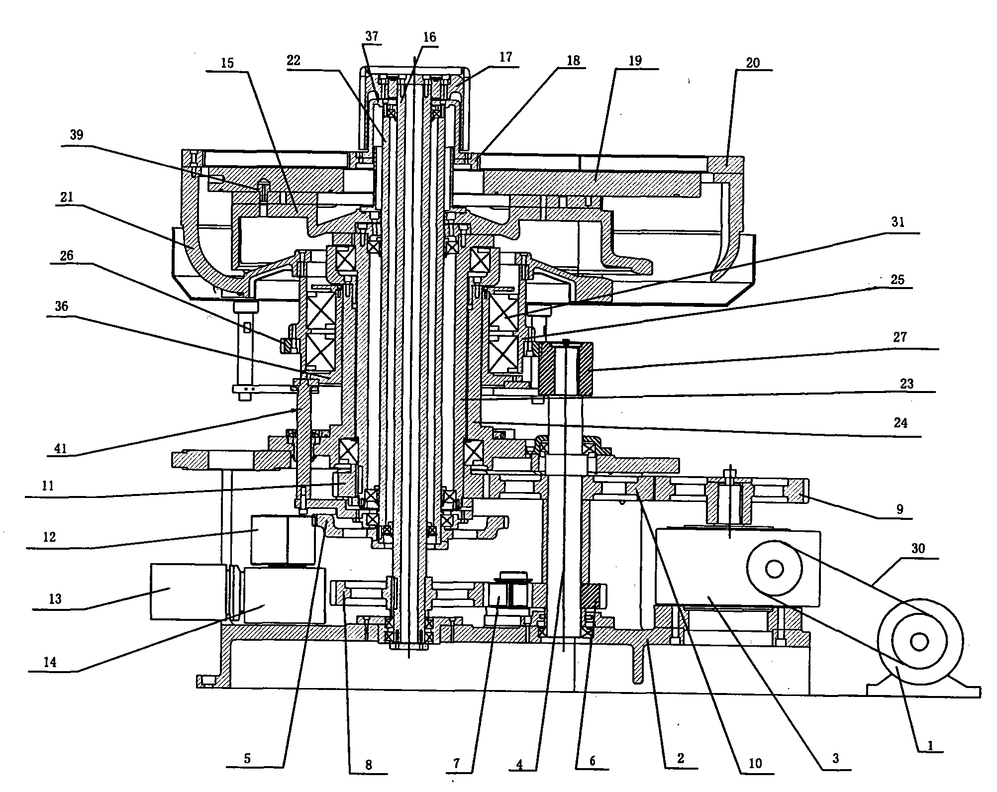
[0025] Example 1, see figure 1 , 5 , the spindle drive system of the CNC precision grinding and polishing machine includes a main motor 1 and a main support 2 arranged on the frame, and the main motor 1 is connected with the main reduction box 3 on the main support 2 through a belt 30 It is connected, and its characteristic is that: the support sleeve 24 is installed on the main support 2, the lifting sleeve 36 is arranged on the outside of the support sleeve 24, and the lower part of the lifting sleeve 36 is provided with a lifting mechanism 41; On the cover 36, the ring gear cover 25 is provided with the ring gear driven gear 26, the ring gear support 21 is fixedly installed on the upper part of the ring gear cover 25, the ring gear 20 is arranged on the ring gear support 21, and the support sleeve 24 is equipped with the lower gear through the bearing. Disc shaft 23, the upper part of the lower disc shaft 23 is fixedly equipped with a tray 15, and the lower disc 19 is arra...

Embodiment 2

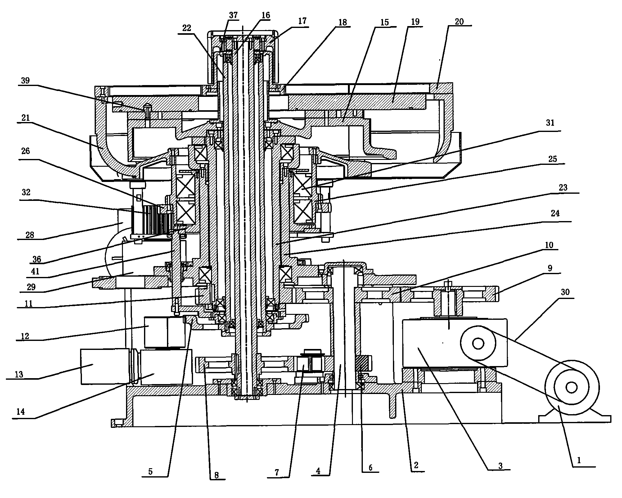
[0029] Example 2, see figure 2 , the difference from embodiment 1 is that the power output shaft of the main reduction box 3 on the main support 2 is provided with a power input gear 9, the power input gear 9 is meshed with the lower disk driving gear 10, and the lower disk driving gear 10 meshes with the driven gear 11 of the lower plate; the driving gear 10 of the lower plate is set on the power transmission shaft 4, the power transmission shaft 4 is set on the main support 2 through the bearing, and the lower end of the power transmission shaft 4 is provided with the upper plate driving gear 6 , The upper plate driving gear 6 meshes with the first idler gear 7 located on the main support 2, and the first idler gear 7 meshes with the upper plate driven gear 8. The main support 2 is also provided with a sun gear motor 13 and a ring gear motor 28, the sun gear motor 13 is connected with the sun gear reduction box 14, and the power output shaft of the sun gear reduction box 14...

Embodiment 3

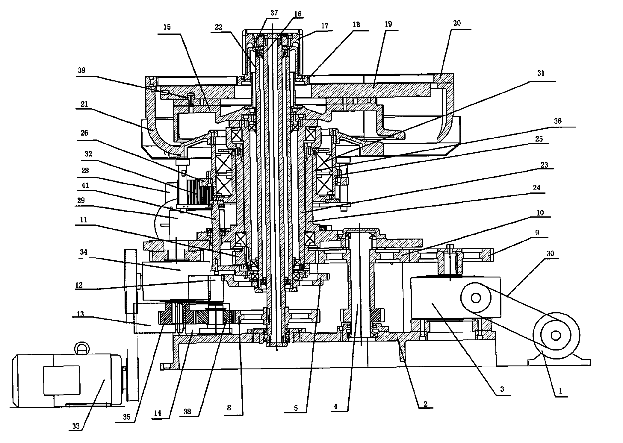
[0030] Example 3, see image 3 , different from Embodiment 1 is that the frame is also provided with an upper plate motor 33, the upper plate motor 33 is connected with the upper plate reduction box 34 by a belt, and the power output shaft of the upper plate reduction box 34 is provided with an upper plate Driving gear 35, the upper disk driving gear 35 meshes with the second idler gear 38, the second idler gear 38 meshes with the upper disk driven gear 8, and the power output shaft of the main reduction box 3 on the main support 2 The power input gear 9 is arranged on the top, and the power input gear 9 meshes with the lower disk driving gear 10, and the lower disk driving gear 10 meshes with the lower disk driven gear 11; the lower disk driving gear 10 is arranged on the power transmission shaft 4, and the power Transmission shaft 4 is located on the main support 2 through bearings. The main support 2 is also provided with a sun gear motor 13 and a ring gear motor 28, the s...


PUM


Abstract

The invention relates to the technical field of numerically-controlled precise grinding polishers and particularly relates to a mainshaft transmission system of the numerically-controlled precise grinding polisher. The mainshaft transmission system comprises a main motor (1) arranged on a stand and a main supporting seat (2); the mainshaft transmission system is characterized in that a supporting sleeve (24) is arranged on the main supporting seat (2); the lower part of a lifting sleeve (36) is provided with a lifting mechanism (41); a gear ring sleeve (25) is arranged on the lifting sleeve (36); the gear ring sleeve (25) is provided with a gear ring driven gear (26); the inside of the supporting sleeve (24) is provided with a lower disc shaft (23) through a bearing; the inside of the lower disc shaft (23) is provided with a solar axle (22) through a bearing; the inside of the solar axle (22) is provided with a central axis (16) through a bearing; the upper part of the central axis (16) is fixedly connected with a dividing wheel (17) for driving an upper disc to rotate; and the lower part of the central axis (16) and the main supporting seat (2) are mounted and positioned through bearings. The mainshaft transmission system can be dragged by one or more servo motors, has wide speed regulation range, higher moving precision, rapider response speed and strong antijamming capacity.

Description

Technical field: [0001] The invention relates to the technical field of numerically controlled precision grinding and polishing machines, and mainly relates to a spindle transmission system of a numerically controlled precision grinding and polishing machine. Background technique: [0002] The traditional grinding and polishing machine is often driven by a single motor, and the transmission of the upper and lower polishing discs and the inner and outer ring gears is realized through the gear transmission system. There are only two speed ratios between the upper and lower polishing discs and the planetary wheels, which limits the change of the processing trajectory of the double-sided polishing machine. Lack of precise control over speed. [0003] Chinese patent 02292538.4, a double-sided polishing machine planetary disk, the planetary disk is provided with three eccentric holes, and three separators are respectively placed in the three eccentric holes. Through the improvemen...

Claims


Application Information

Patent Timeline
IPC IPC(8): B24B47/12
Inventor 金万斌梁春刘文平张宝玉
Owner LANZHOU RAPID INDGRPCO
Why Eureka
Try Eureka