Fiber optic gyro framework designed according to sectorization

A fiber optic gyroscope and functional partitioning technology, applied in Sagnac effect gyroscopes and other directions, can solve problems such as unreasonable conduction and heat flow direction, affecting the accuracy of fiber optic gyroscopes, and less consideration of air tightness functional requirements.

Inactive Publication Date: 2009-12-09
BEIHANG UNIV
View PDF0 Cites 27 Cited by
  • Summary
  • Abstract
  • Description
  • Claims
  • Application Information

AI Technical Summary

Problems solved by technology

[0004] The current framework for fiber optic gyroscopes seldom considers airtight functional requirements in terms of structural layout. (like Figure 1A As shown) there are no strict requirements for the arrangement, when vibration, air pressure changes, and ambient temperature changes, it will have a non-reciprocal effect on the optical device with the optical fiber, and at the same time, the unreasonable conduction and heat flow direction will cause the internal generation of the optical fiber coil 1A The uneven distribution of stress and temperature fields seriously affects the output accuracy of the fiber optic gyroscope

Method used


Image

  • Fiber optic gyro framework designed according to sectorization
  • Fiber optic gyro framework designed according to sectorization
  • Fiber optic gyro framework designed according to sectorization

Examples


Embodiment Construction

[0039] The present invention will be further described in detail below in conjunction with the accompanying drawings.

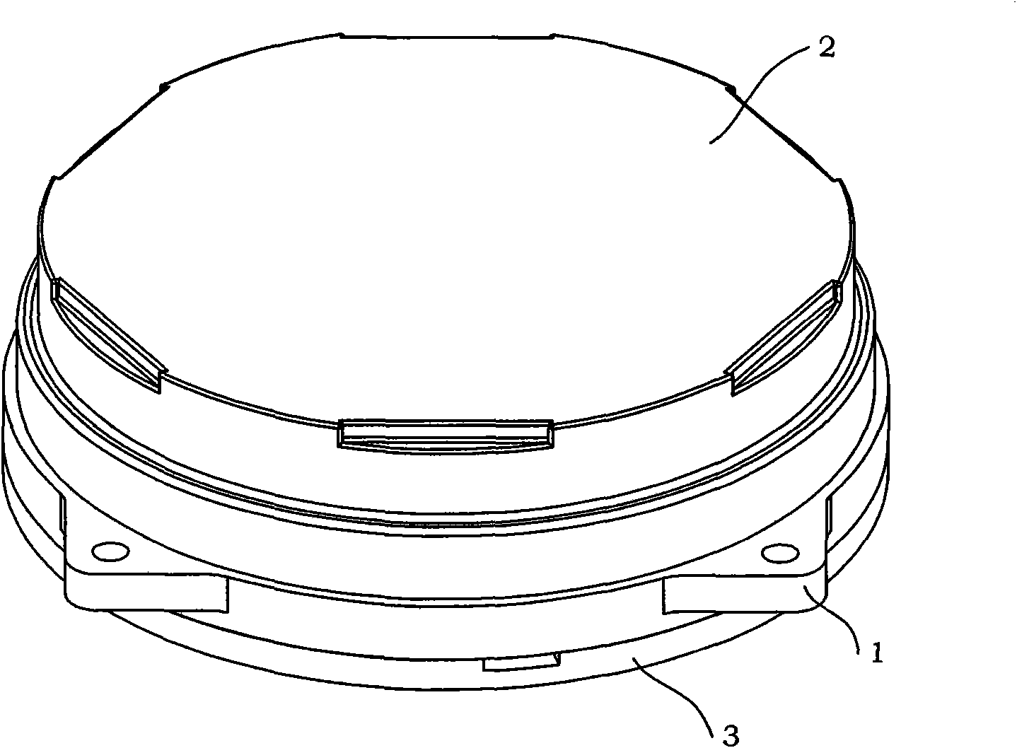
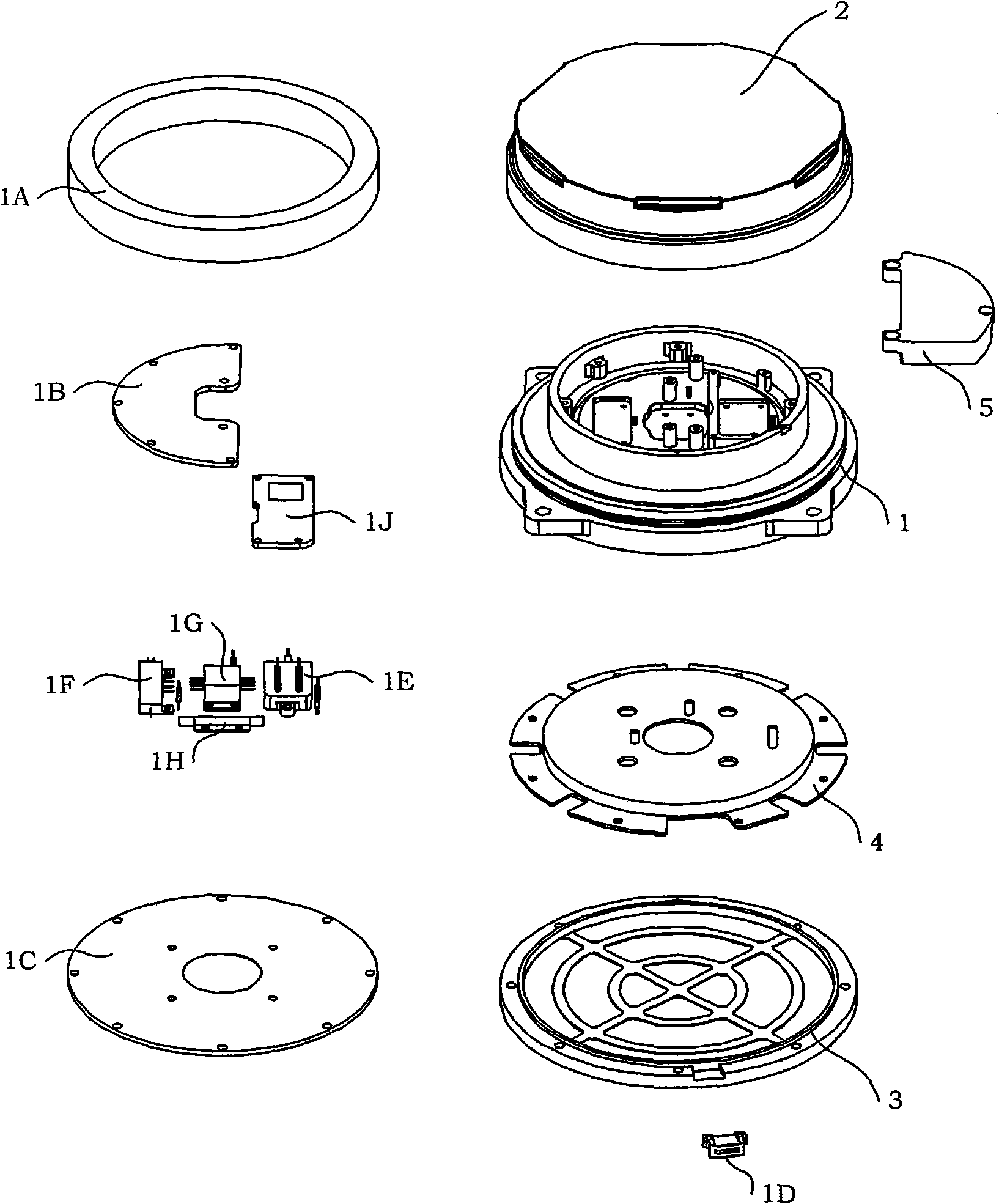
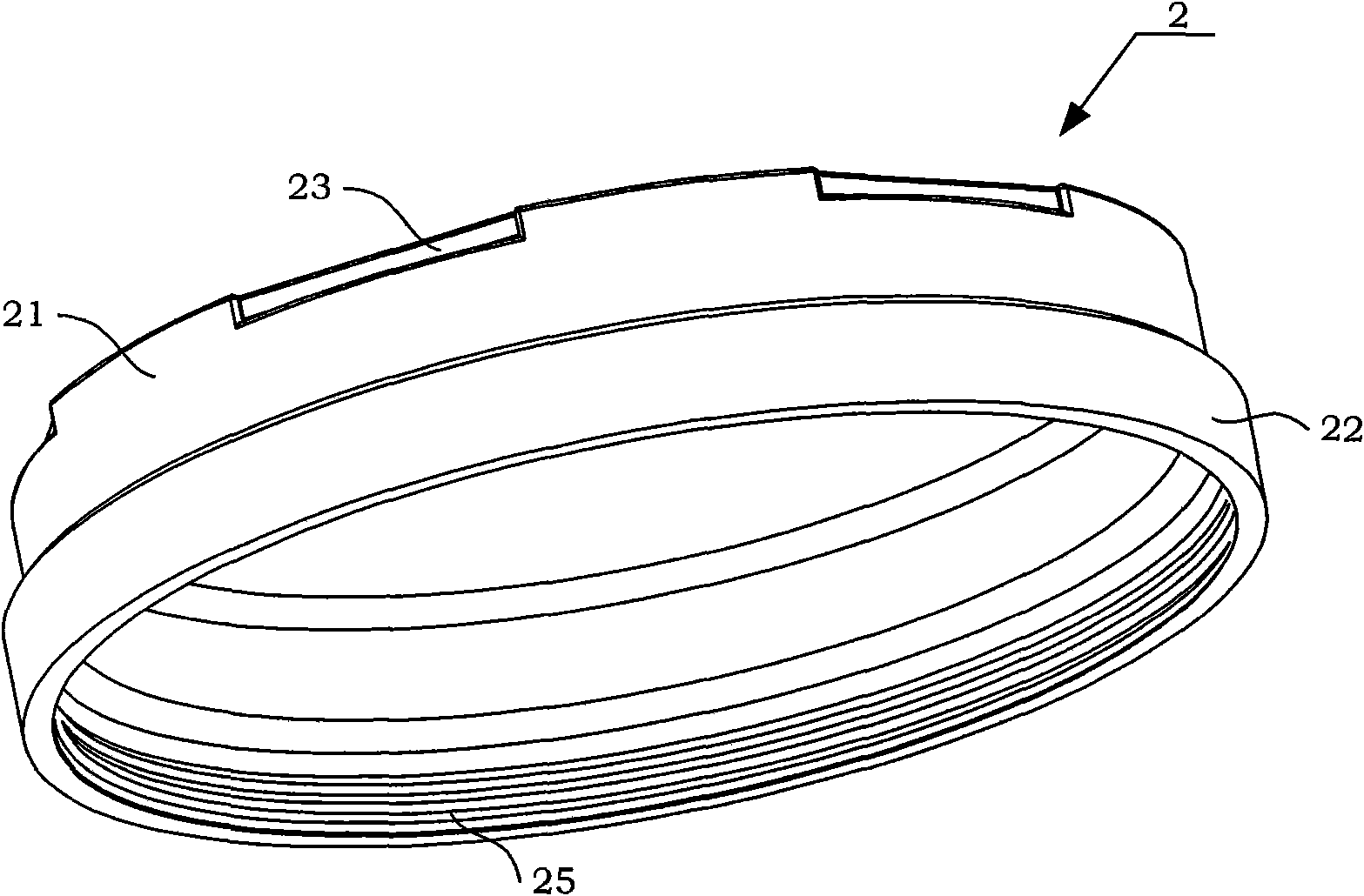
[0040] see figure 1 As shown, the present invention is a fiber optic gyroscope skeleton designed according to functional divisions. The skeleton includes a skeleton body 1 , an upper cover 2 , a lower cover 3 , a magnetic shield 4 and a front cover 5 . The upper cover 2 is screwed on the B circular platform section 12 of the frame body 1; the front cover plate 5 is installed on the L-shaped partition 104 in the frame body 1, and the magnetic shield 4 is placed between the frame body 1 and the lower cover 3 , and the magnetic shield 4 is installed on the first step of the skeleton body 1 , and the lower cover 3 is installed at the lower end of the skeleton body 1 .

[0041] (1) Skeleton body 1

[0042] see figure 1 , Figure 1A , Figure 6 , Figure 6A , Figure 6B As shown, the skeleton body 1 is integrally processed into a molded part, and is a disc ...


PUM


Abstract

The invention discloses a fiber optic gyro framework designed according to sectorization, comprising an upper cover (2), a framework body (1), a magnetic shield (4), a front-laid cover (5) and a lower cover (3); the upper cover (2) is connected to a B cone frustum (12) of the framework body (1) by threads, the front-laid cover (5) is mounted on an L-shape clapboard (104) in the framework body (1), the magnetic shield (4) is positioned between the framework body (1) and the lower cover (3), and the lower cover (3) is mounted at the lower end of the framework body (1). The framework body (1) designed by the invention is laid out with regions according to the functions realized by an element to be placed, the framework body (1) under intact construction is divided into an upper layer cavity (16A) and a lower layer cavity (16B) by a cavity separating plate (16), the upper layer cavity (16A) is mainly used for placing elements with optical fiber such as an SLD light source (1G), a coupler (1H), a Y waveguide (1F), a photoelectric detector (1E) as well as a light source drive circuit (1B), a front-laid circuit (1J) and the like; and the lower layer cavity (16B) is used for placing the magnetic shield (4) and signal circuit (1C).

Description

technical field [0001] The present invention relates to an optical fiber gyroscope skeleton, more particularly, a fiber optic gyroscope skeleton designed according to functional divisions. Background technique [0002] The interferometric fiber optic gyroscope is a Sagnac interferometer, which is a sensor used to detect the angular velocity of the carrier. It has the advantages of all solid state, high reliability, large dynamic range, and small size. The development of medium and high-precision application fields has become the main instrument in inertial navigation and strategic application fields. [0003] The main working principle of the interferometric fiber optic gyroscope is that the fiber optic coil in the fiber optic gyroscope is sensitive to the rotation of the carrier, and the Sagnac phase shift generated is φ R = 4 πRL λ ‾ ...

Claims


Application Information

Patent Timeline
Patent Type & Authority Applications(China)
IPC IPC(8): G01C19/72
Inventor 刘海霞贾明杨玉生欧攀牛燕雄李惠宋凝芳
Owner BEIHANG UNIV
Why Eureka
Try Eureka