Adjustable glow monitoring system of glow equipment

A monitoring system and adjustable technology, applied in control/regulation systems, light control, climate sustainability, etc., can solve problems such as unclean silicon etching, interference with monitoring system signals, product abnormalities, etc., to achieve monitoring reliability Enhanced, stabilized reaction conditions, less prone to misoperation

Inactive Publication Date: 2009-12-09
扬州晶澳太阳能研发有限公司
View PDF0 Cites 2 Cited by
  • Summary
  • Abstract
  • Description
  • Claims
  • Application Information

AI Technical Summary

Problems solved by technology

[0002] In the existing silicon solar cell manufacturing process, general domestic etching machines and flat-plate PECVD equipment (plasma enhanced chemical vapor deposition equipment) do not have the functions of monitoring and real-time data collection for plasma etching and PECVD deposition and coating processes, but In the actual production process, due to factors such as the above-mentioned etching machine and flat-panel PECVD and other glow equipment failures, staff operating errors, and power supply failures, etc., the glow intensity in the glow equipment cavity often fluctuates. Cause product abnormalities, resulting in the production of products that do not meet the quality requirements. Taking the etching machine as an example, due to various unstable factors, such as changes in process gas flow, changes in vacuum pressure in the reaction chamber, accumulation of dust on quartz parts and Aging and power changes of microwave power supply will affect the quality of silicon wafers, and the changes of the above factors can also be reflected in the changes of glow. These unstable factors cause defects such as unclean etching of silicon wafers. Defects will have a great impact on the quality of solar cells and directly lead to unqualified solar cell products
[0003] For a long time, the monitoring of the plasma glow reaction process and the control of the glow power have been the technical problems that the solar cell manufacturing industry has been dreaming of but are difficult to solve. At present, the general glow monitoring method is to monitor the glow power. Both sample current or voltage to achieve the purpose of monitoring through feedback comparison, but this monitoring method has the following defects: (1) Because the microwave power supply is at a high frequency (up to thousands of Hz) and high voltage (up to more than one thousand volts), so The microwave power supply will interfere with the signal of the monitoring system and cause the wrong action of the monitoring system, so this monitoring method is not very reliable; (2) Because only the power change of the microwave power supply is monitored, other changes cannot be effectively monitored, so The state monitoring of the glow reaction cannot be directly realized, and more stable reaction conditions cannot be realized, and the glow intensity is still prone to fluctuations; (3) Due to the aforementioned reasons, the existing monitoring system cannot know whether other parameters are stable condition
[0004] To sum up, the existing glow monitoring method that only monitors the glow power cannot effectively monitor the plasma glow reaction process and the glow power

Method used


Image

  • Adjustable glow monitoring system of glow equipment
  • Adjustable glow monitoring system of glow equipment

Examples


Embodiment 1

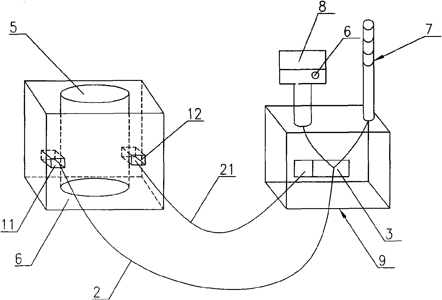
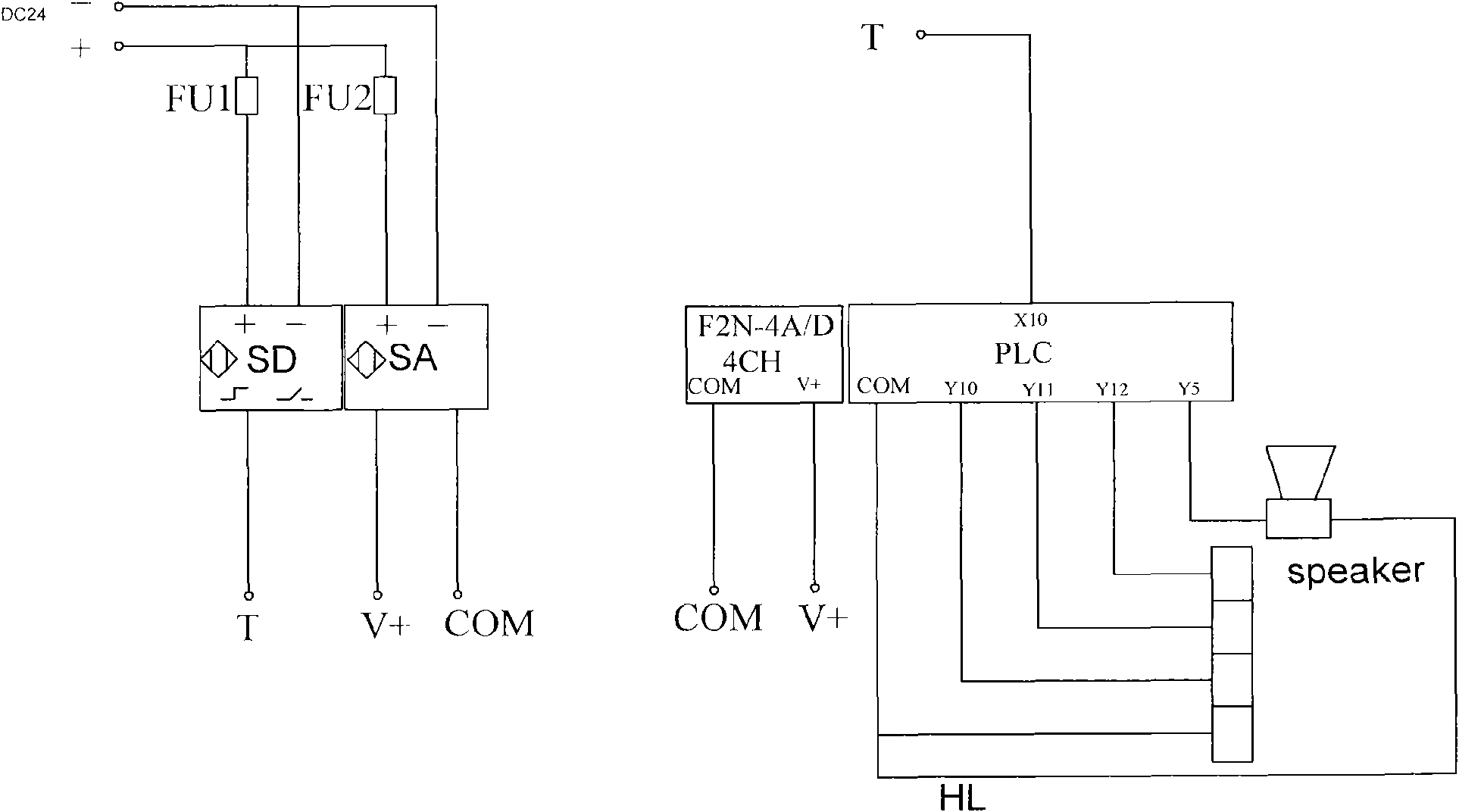
[0025] like figure 1 As shown, a glow device adjustable glow monitoring system of the present invention includes a photosensitive sensor for monitoring glow intensity, a connecting cable and a controller 3, the controller 3 adopts a programmable logic controller (PLC), and the photosensitive sensor includes The switch quantity photosensitive sensor 11 and the analog quantity photosensitive sensor 12, the programmable controller is equipped with a warning device connected with its power, the warning device adopts the buzzer 6 and the indicator light 7 which shows different alarm levels with different color lamp tubes, the switch quantity The photosensitive sensor 11 has a control circuit for setting the glow intensity, and the set intensity is regulated by a regulator in the control circuit. The switching value photosensitive sensor 11 and the analog quantity photosensitive sensor 12 are respectively connected to the programmable The controller; the off-quantity photosensitive ...

Embodiment 2

[0032] The difference between this embodiment and Embodiment 1 is that the photosensitive sensor only adopts the switching value photosensitive sensor, the distance between the switching value photosensitive sensor and the side wall of the glow generating cavity is 5cm, and the controller adopts an industrial computer. When the glow intensity monitored by the photosensitive sensor rises or falls to the set value of the glow intensity, the switch value photosensitive sensor sends a switch signal to the industrial computer, and the industrial computer receives the signal, and realizes the buzzing by calculating the pre-programmed program indicator and indicator light.

Embodiment 3

[0034] The difference between this embodiment and Embodiment 1 is that the photosensitive sensor only uses an analog photosensitive sensor, the distance between the analog photosensitive sensor and the side wall of the glow generating cavity is 20 cm, and the analog photosensitive sensor controls the glow intensity. The analog quantity is converted and the converted signal is sent to the programmable controller. The programmable controller converts the converted signal into the actual power of the glow power supply through the corresponding relationship between the converted signal and the glow power supply obtained in advance, that is, the glow power supply Power data recording and control of the output of the glow power supply to realize the adjustment of the glow intensity.


PUM


Abstract

The invention discloses an adjustable glow monitoring system of glow equipment, comprising a photosensitive sensor, a connecting cable and a controller, wherein, the photosensitive sensor is used for monitoring glow intensity, the photosensitive sensor is connected with the controller through the connecting cable and is arranged outside of a glow generating chamber in the glow equipment, and the photosensitive sensor is used for monitoring plasma glow intensity of the glow generating chamber to acquire a monitoring signal which is transmitted to the controller through the connecting cable, corresponding manipulating action is adopted after the monitoring signal is received by the controller. the invention adopts the photosensitive sensor to directly monitor on the glow intensity, has little interference and strong reliability, and can not cause malfunction; the invention directly realizes monitoring on the glow reaction, and then realizes the stable reacting condition, thus avoiding the glow fluctuation caused by the fault of the glow equipment and manual operation failure and ensuring the quality of the solar cell products.

Description

technical field [0001] The invention relates to a monitoring system, which is especially suitable for monitoring the working status of equipment with plasma glow characteristics such as plasma etching and plasma coating and collecting relevant data in real time during the manufacturing process of silicon solar cells. Background technique [0002] In the existing silicon solar cell manufacturing process, general domestic etching machines and flat-plate PECVD equipment (plasma enhanced chemical vapor deposition equipment) do not have the functions of monitoring and real-time data collection for plasma etching and PECVD deposition and coating processes, but In the actual production process, due to factors such as the above-mentioned etching machine and flat-panel PECVD and other glow equipment failures, staff operating errors, and power supply failures, etc., the glow intensity in the glow equipment cavity often fluctuates. Cause product abnormalities, resulting in the producti...

Claims


Application Information

Patent Timeline
Patent Type & Authority Applications(China)
IPC IPC(8): G05D25/02H01L31/18
CPCY02P70/50
Inventor 戴德鹏
Owner 扬州晶澳太阳能研发有限公司
Why Eureka
Try Eureka