Distributed node video monitoring system and management method thereof

A video surveillance system and distributed node technology, applied in closed-circuit television systems, transmission systems, televisions, etc., can solve problems such as device authority conflicts, service interruptions, and system crashes, and achieve access bottlenecks, reduced access, and strong expansion capabilities Effect

Active Publication Date: 2009-12-09
ZTE CORP
View PDF0 Cites 13 Cited by
  • Summary
  • Abstract
  • Description
  • Claims
  • Application Information

AI Technical Summary

Problems solved by technology

[0006] 1. The RGM Manager module concentrates too much business processing, which can easily become the performance bottleneck of the system
[0007] 2. The data interaction between the database server and each subsystem is too frequent. When the amount of data is large, it is easy to form a bottleneck of the database
[0008] 3. Does not support large-capacity devices
According to the existing structure of the commercial video surveillance system, when large-capacity front-end equipment access, media forwarding, customer access, and video storage are required, the business will be processed in the registration management (RGM Manager) module of the system, which causes a lot of damage to the system. High pressure often causes response delays and system crashes
[0009] 4. The scalability of the system is not good
[0010] 5. Poor scalability of the platform
When this happens, it usually leads to data conflicts when a new device is connected; because the status information of the front-end device is inconsistent with the database data, the monitoring cannot be performed normally; the device permissions saved by each node conflict, so that the user accesses different nodes. The obtained device permission information is displayed differently
When these situations occur, the existing system can only restart the node device to re-acquire data to maintain consistency, and frequent device restarts will cause business interruption, which is unacceptable to users

Method used


Image

  • Distributed node video monitoring system and management method thereof
  • Distributed node video monitoring system and management method thereof
  • Distributed node video monitoring system and management method thereof

Examples


Embodiment Construction

[0055] The present invention will be described in further detail below in conjunction with the accompanying drawings and specific embodiments.

[0056] The present invention provides a method to ensure the data consistency of each node to improve the distributed node video monitoring system, mainly based on the structure adopted by the existing video monitoring system, optimizes and reorganizes the structure, and proposes a new distributed node structure And two synchronization mechanisms, the synchronization mechanism solves the data consistency problem generated by the distributed structure. The invention can well solve some defects of the existing video monitoring system.

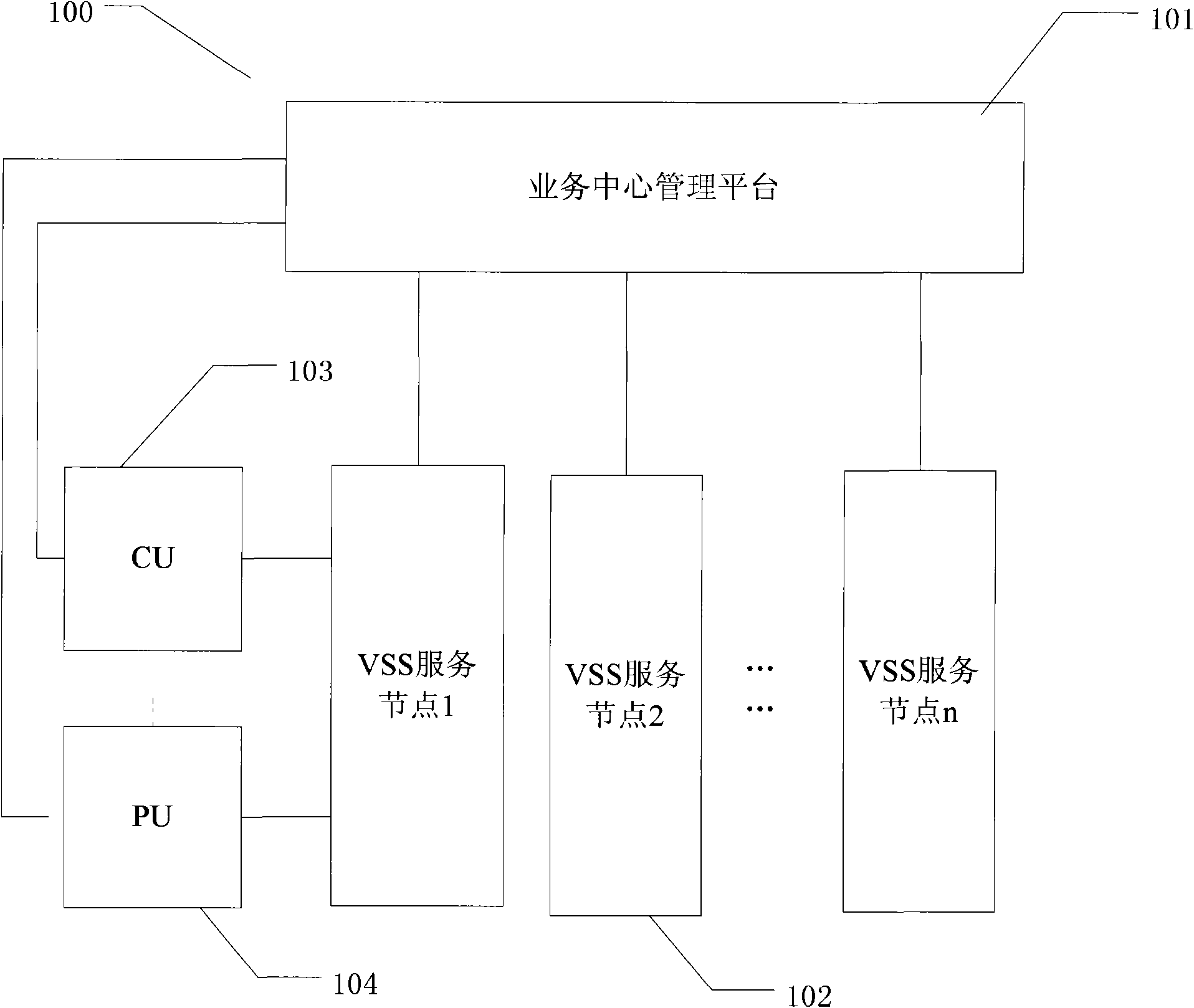
[0057] One embodiment of the present invention provides a video monitoring system, which adopts a distributed node structure and a management method for maintaining node data consistency, such as figure 2 As shown, its components include: a business center management platform 101 , multiple VSS service...


PUM


Abstract

The invention relates to a distributed node video monitoring system, which comprises a plurality of VSS service nodes and a service center management platform for managing the plurality of the VSS service nodes, wherein each VSS service node is also connected with a device front end PU for acquiring video monitoring information and a client CU for showing the video monitoring information; the client CU and the device front end PU directly access each VSS service node through the service center management platform to acquire data; and the plurality of the VSS service nodes are kept synchronous with the data in the service center management platform. The invention discloses a novel distributed node structure and two synchronization mechanisms based on the structure adopted by the prior video monitoring system, and the distributed node video monitoring system is perfected by ensuring the data consistency of each node so that certain defects of the prior video monitoring system can be overcome well.

Description

technical field [0001] The invention relates to a distributed node video monitoring system and a management method thereof. Background technique [0002] Network video monitoring service is a value-added service based on broadband network remote image monitoring, transmission, storage and management. This business utilizes broadband network to connect scattered and independent image acquisition points to the Internet, so as to realize unified monitoring, unified storage, unified management and resource sharing across regions and in the whole range. The network video surveillance system meets the needs of public surveillance and professional surveillance at the same time. With independent networking, it can not only carry out video surveillance services on mobile streaming media, but also carry out video surveillance services on interactive Internet TV (IPTV) networks. [0003] Existing video surveillance systems are generally composed of multiple subsystems. If the cooperat...

Claims


Application Information

Patent Timeline
Patent Type & Authority Applications(China)
IPC IPC(8): H04N7/18H04L12/28
CPCH04L41/5038H04L65/00H04N21/00H04L29/06333H04L41/509H04N7/18H04L65/1073H04L29/08558G08B13/19656H04L67/12H04N7/181H04L43/55
Inventor 冯燕青余涛
Owner ZTE CORP
Why Eureka
Try Eureka