
Sub-pixel motion estimation device and method therefor

A motion estimation and sub-pixel technology, applied in image communication, television, electrical components, etc., can solve problems such as prolonging the search process, affecting the compression efficiency of the coding system, and increasing the complexity of motion estimation operations

Inactive Publication Date: 2009-12-09
HANGZHOU SILAN MICROELECTRONICS
View PDF0 Cites 10 Cited by
  • Summary
  • Abstract
  • Description
  • Claims
  • Application Information

AI Technical Summary

Problems solved by technology

[0006] However, the use of variable macroblock segmentation mode and smaller precision sub-pixel, while improving the compression rate of the coding system, the motion estimation also leads to a significant increase in the computational complexity of motion estimation, prolonging the entire search process, if the motion It is estimated that as a first-level pipeline, it will be the bottleneck of the entire encoding system, and currently there are few hardware acceleration modules that can fully utilize new features and maintain the real-time performance of the encoding system, especially for multiple reference frames. The calculation will lead to a decrease in the performance of the encoding system, and real-time encoding cannot be achieved
[0007] In order to ensure real-time encoding, some schemes narrow the range of the search window. Although this can greatly reduce the complexity of motion estimation and reduce the constraints of this level of pipeline on the system, the range of the search window is reduced from the whole pixel search. Small, which reduces the probability of obtaining the best match and affects the compression efficiency of the coding system

Method used


Image

  • Sub-pixel motion estimation device and method therefor
  • Sub-pixel motion estimation device and method therefor
  • Sub-pixel motion estimation device and method therefor

Examples


Embodiment Construction

[0063] The content of the present invention will be further described below in conjunction with the accompanying drawings.

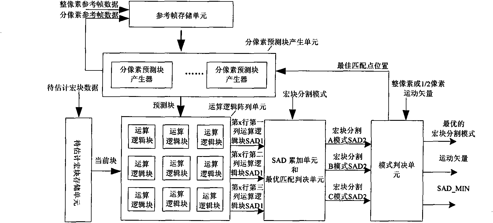
[0064] A sub-pixel motion estimation device, such as figure 2 As shown, it includes a macroblock storage unit to be estimated (11), a reference frame storage unit (12), a sub-pixel prediction block generation unit (13), an operation logic array unit (14), an SAD accumulation unit (15), an optimal matching Judgment unit (16) and mode judgment unit (17):

[0065] The macroblock to be estimated storage unit (11) stores the macroblock to be estimated, and continuously calls out pixel sub-blocks with a size of NxN (4x4) from the macroblock to be estimated as the current block, and the current block is input to the arithmetic logic array unit one by one (14);

[0066] The reference frame storage unit (12) stores an integer pixel or sub-pixel reference frame image, and according to the position of the current block in the macroblock to be estimated, the inte...


PUM


Abstract

The invention provides a sub-pixel motion estimation device and a method therefor; the device comprises a macroblock storage unit to be estimated, a reference frame storage unit, a sub-pixel prediction block generation unit, an arithmetic and logic array unit, an SAD accumulation unit, an optimal matching decision unit and a mode deciding unit, while another pattern of the device comprises the macroblock storage unit to be estimated, the reference frame storage unit, the sub-pixel prediction block generation unit, the arithmetic and logic array unit, the SAD accumulation unit, a mode select unit and the optimal matching deciding unit. The invention balances the search range and the search accuracy of the motion estimation, lowers the calculating complexity, shortens the search time, ensures the instantaneity of a coding system, the whole motion estimation operation is performed in a short cycle, less resources are occupied without damaging the coding performance, little impact is imposed on compression efficiency of an encoder, so that choices can be made by weighing and balancing among performance, power consumption and area of the encoder; in addition, the device and method of the invention have strong versatility and reusability.

Description

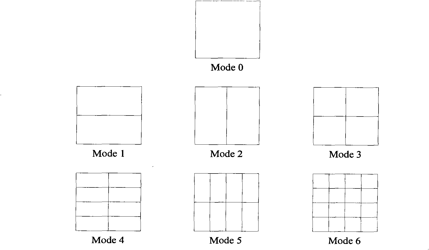
technical field [0001] The invention relates to the realization of motion estimation in digital video coding, especially a method and device for sub-pixel motion estimation in inter-frame prediction. Background technique [0002] In digital video coding, inter-frame prediction based on motion estimation algorithm can reduce redundant information in time of video data. This method has been widely used in video coding standards such as MPEG-x and H.26x. Generally speaking, the computational load of inter-frame prediction will account for 60%-80% of the load of the entire coding system. Therefore, the hard acceleration module of motion estimation implemented with a dedicated ASIC architecture is widely used in the coding system. [0003] Most of the currently existing motion estimation architectures are for fixed macroblock segmentation modes. The common fixed macroblock segmentation modes are: 8x8 structure with 8 sampling points in the horizontal direction and 16 sampling poi...

Claims


Application Information

Patent Timeline
IPC IPC(8): H04N7/26H04N19/523
Inventor 李鑫锢
Owner HANGZHOU SILAN MICROELECTRONICS
Learn More