
Breakdown diagnosing device and breakdown diagnosing method of nox sensor

A technology of fault diagnosis device and sensor, which is applied in the direction of diagnosis device, chemical instrument and method, noise reduction device, etc. of exhaust treatment device, which can solve problems affecting drivability, fuel consumption degradation, etc., and achieve reliability improvement and high-efficiency failure The effect of diagnosis

Active Publication Date: 2009-12-09
BOSCH CORP
View PDF1 Cites 17 Cited by
  • Summary
  • Abstract
  • Description
  • Claims
  • Application Information

AI Technical Summary

Problems solved by technology

That is, during the operation of the internal combustion engine, it is necessary to change the operating state in order to appropriately determine the responsiveness of the sensor, which may affect drivability or deteriorate fuel consumption.

Method used


Image

  • Breakdown diagnosing device and breakdown diagnosing method of nox sensor
  • Breakdown diagnosing device and breakdown diagnosing method of nox sensor
  • Breakdown diagnosing device and breakdown diagnosing method of nox sensor

Examples


no. 1 approach

[0045] 1. NO X Sensor Fault Diagnosis Device

[0046] (1) The overall composition of the exhaust purification system

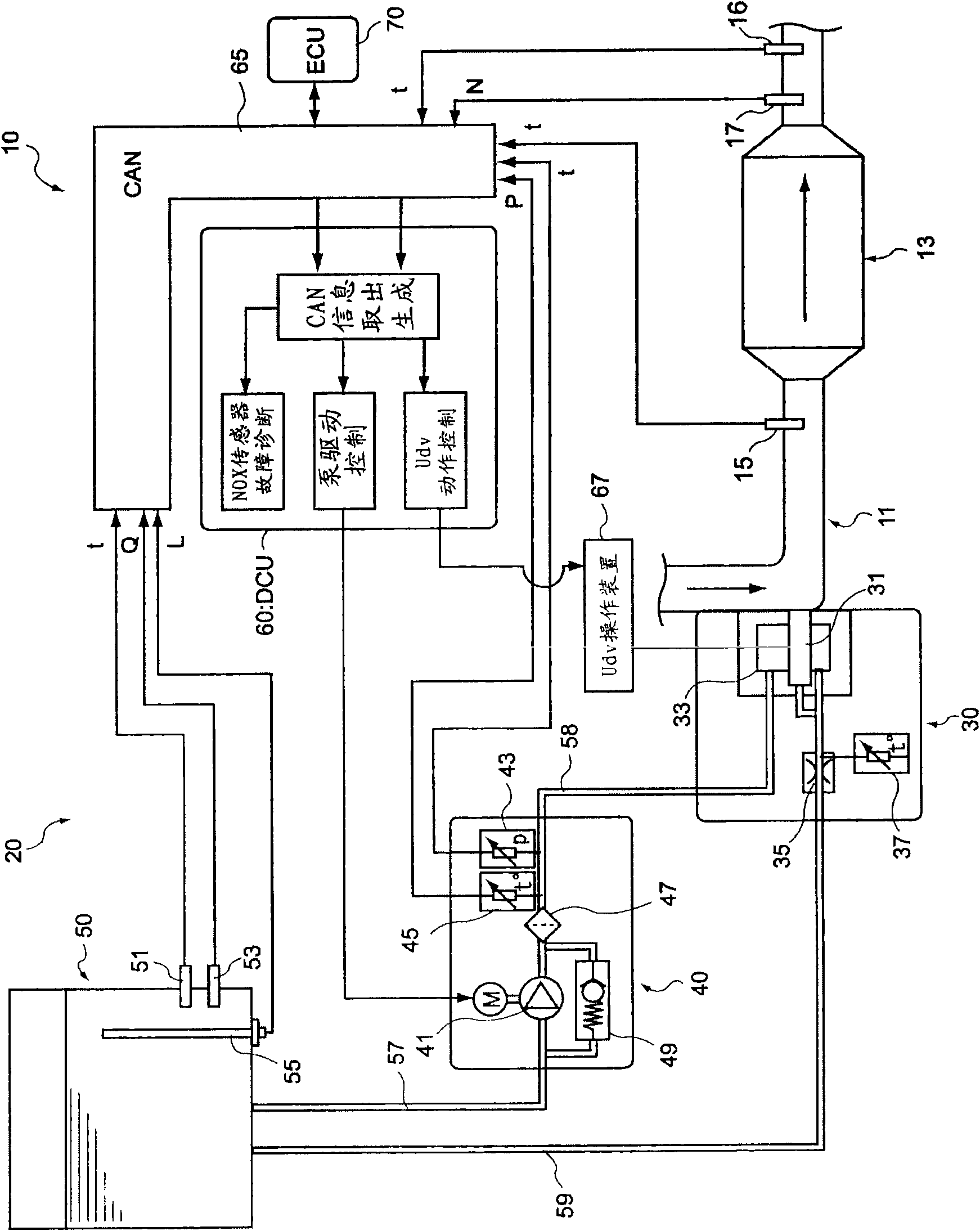
[0047] First, refer to figure 1 Description of the NO with the first embodiment of the present invention X A configuration example of an exhaust purification system (hereinafter, sometimes simply referred to as a "system") of a fault diagnosis device for a sensor.

[0048] figure 1 The exhaust purification system 10 shown uses urea aqueous solution as a reducing agent, and makes the exhaust gas pass through the NO together with the reducing agent. X Catalyst 13 to selectively reduce NO X Exhaust purification system 10. The exhaust purification system 10 has: NO X The catalyst 13 is arranged in the middle of the exhaust passage 11 connected to the internal combustion engine and is used for selectively reducing NO contained in the exhaust gas X ; Reductant supply device 20, containing for NO X The upstream side of the catalyst 13 injects the reducing ...

no. 2 Embodiment approach

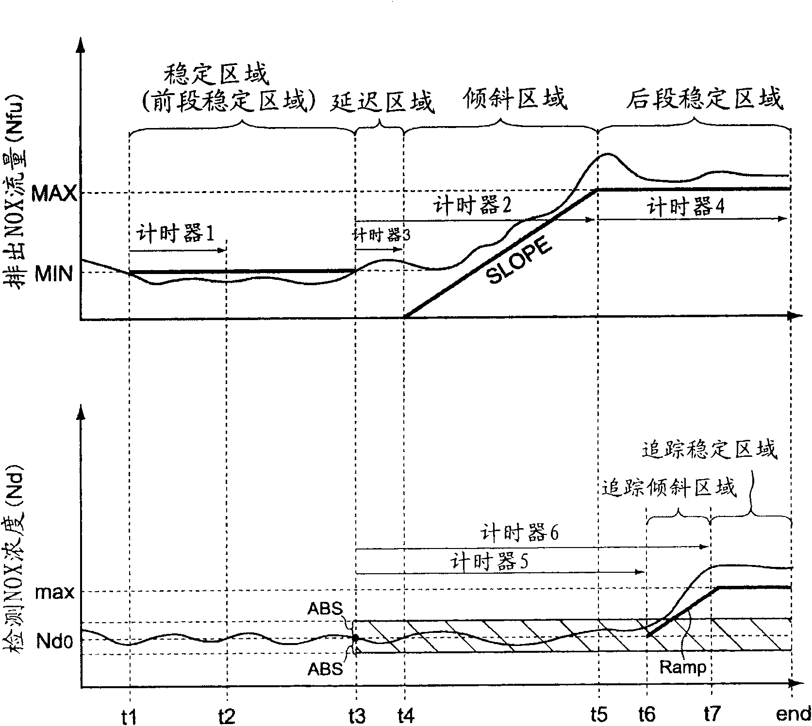
[0111] NO in this embodiment X The method of fault diagnosis of the sensor, as described above, is the NO X Catalysts with relatively small capacity for NO in SCR systems X Sensor fault diagnosis method. That is to say, in this embodiment, when increasing the exhaust NO X After flow to by configuring in NO X NO on the downstream side of the catalyst X NO detected by the sensor X The flow tracking time is shortened, and the elapsed time of timer 2 is set longer than the elapsed time of timer 5 .

[0112] Below, according to Figure 7 ~ Figure 9 The flow of the present invention will be described focusing on points different from those of the first embodiment.

[0113] In this embodiment, until the timers 2, 3, 5, and 6 are activated, the same steps as steps S100 to S113 in the first embodiment are performed (see Figure 4 ). After the timers 2, 3, 5, and 6 are operated, the steps between step S154 and step S161 are carried out in the same manner as the steps between st...


PUM


Abstract

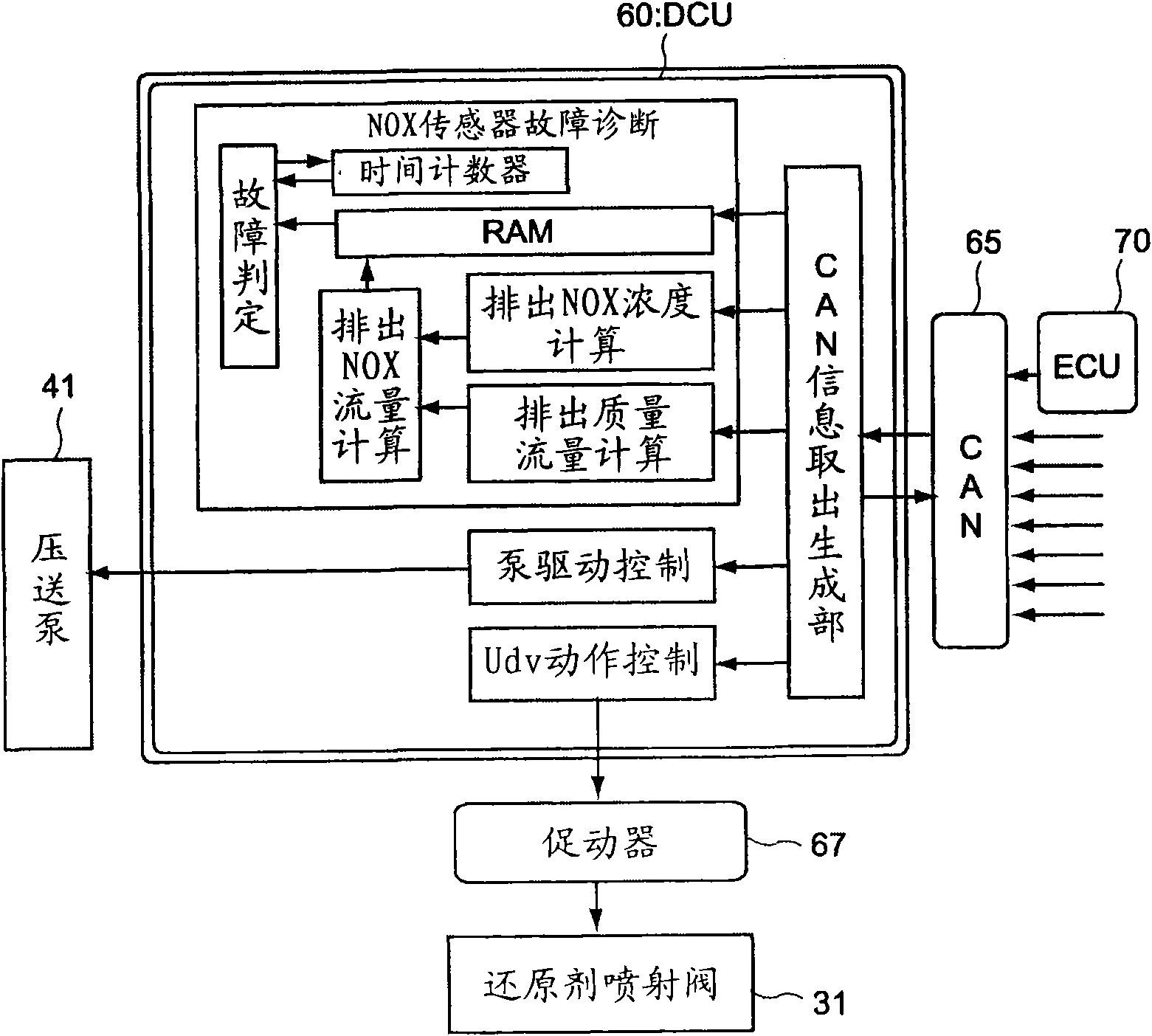
There is provided an NO x sensor trouble diagnosis device and an NO x trouble diagnosis method that can perform trouble diagnosis on a timely basis without intentionally creating any diagnosis mode during operation of an internal combustion engine and without deterioration of drivability and fuel consumption. The device includes an exhaust NO x flow rate calculating and storing means for calculating and storing an exhaust NO x flow rate discharged from an internal combustion engine per unit time, detected NO x concentration storing means for storing a detected NO x concentration detected by an NO x sensor, and trouble determining means for defining a reference pattern as a time-lapse variation reference of the exhaust NO x flow rate and a follow pattern as a time-lapse variation reference of the detected NO x concentration detected by the NO x sensor, and determining whether the detected NO x concentration undergoes a transition while having a predetermined relation with the follow pattern when the exhaust NO x flow rate undergoes a transition while having a predetermined relation with the reference pattern in a case where the internal combustion engine is in a normal operation mode, thereby determining the responsiveness of the NO x sensor.

Description

technical field [0001] The present invention relates to a NO X Sensor fault diagnosis device and NO X Sensor fault diagnosis method. In particular, it relates to a method for performing NO with high precision X Sensor Fault Diagnosis NO X Sensor fault diagnosis device and NO X Sensor fault diagnosis method. Background technique [0002] Conventionally, the exhaust gas discharged from internal combustion engines such as diesel engines contains soot particles (PM) and NO which may affect the environment. X (NO and NO 2 )Wait. At this time, as the NO X The exhaust purification system has a NO X Catalyst exhaust purification system. [0003] As such an exhaust purification system, it is known to use NO X Exhaust gas purification systems that store catalysts and SCR (Selective Catalytic Reduction) systems that use selective reduction catalysts. Use NO X The exhaust purification system of the storage catalyst absorbs NO in the exhaust gas when the air-fuel ratio of th...

Claims


Application Information

Patent Timeline
Patent Type & Authority Applications(China)
IPC IPC(8): F01N3/20B01D53/86B01D53/94F01N3/08F01N3/18F01N3/24F02D41/14F02D45/00
CPCF02D41/146Y02T10/47Y02T10/20F01N3/0807F01N11/00F01N2900/14Y02C20/10F02D41/222Y02T10/40F02D41/1461F02D41/1462F01N2560/026F01N2900/0416Y02T10/12B01D53/86B01D53/94F01N3/08F01N3/18
Inventor 北泽英一
Owner BOSCH CORP
Learn More