

Confocal type laser test head based on time difference method
A technology of laser measuring head and time difference, which is applied in the direction of optics, measuring devices, optical components, etc., can solve the problems of unsuitable measurement, small range, large shape, etc., achieve the effect of compact and beautiful appearance, and make up for manufacturing errors
Inactive Publication Date: 2009-12-16
TIANJIN UNIV
View PDF0 Cites 6 Cited by
- Summary
- Abstract
- Description
- Claims
- Application Information
AI Technical Summary
Problems solved by technology
Most of the confocal method probes have the disadvantages of small measuring range, large measuring light spot and large shape, so they are not suitable for measuring large curved surfaces.
Method used
View moreImage
Smart ImageViewing Examples

Examples
Embodiment
[0024] Use this probe to measure two gauge blocks with different standard values placed on the same plane, and the actual height difference between the two is 10 μm. Shoot the measuring beam of the measuring head on the above two gauge blocks respectively, and then record the measuring result of the measuring head, the result of the two measurements is the height difference obtained by the measuring head. The average value after multiple measurements is 10.7 μm, and the standard deviation is 0.5, which meets the measurement accuracy requirement of 3 μm required by the design.
Login to View More PUM
 Abstract
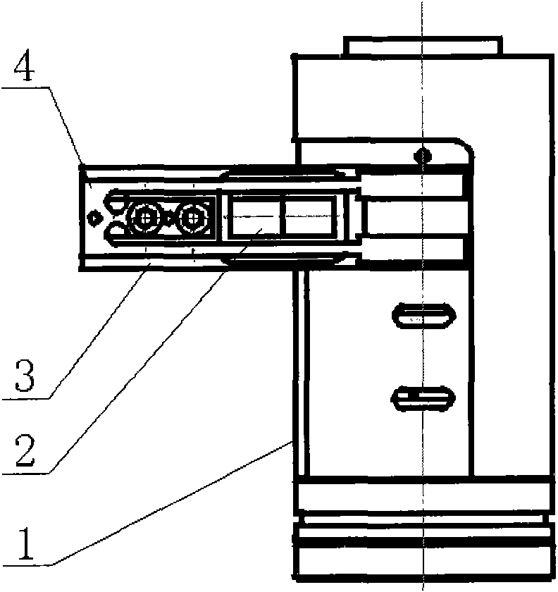
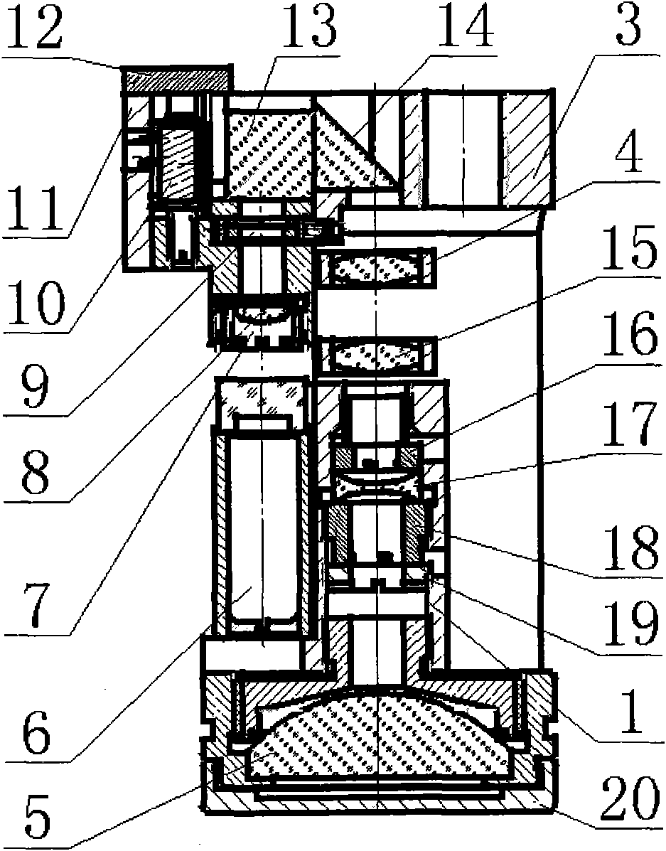
The invention provides a confocal type laser test head based on a time difference method. A main mechanism of the test head comprises a laser, a splitting prism, a tuning fork lens, a coil component and a photoelectric receiver positioned in a photoelectric receiver sleeve, wherein a laser of the main mechanism is positioned inside a laser sleeve; an optical filter is positioned above the laser to form a laser component; the rear part of the laser component is provided with an aperture diaphragm component; the rear part of the aperture diaphragm component is provided with a plano-convex lens component; the rear part of the tuning fork lens is provided with a parallel light adjusting mechanism; the rear part of the parallel light adjusting mechanism is provided with an aspherical objective lens component; and the front end of the formed photoelectric receiver component is connected with an adjusting mechanism for radially adjusting a top thread. The confocal laser test head has the advantages of folding a light path to have compact shape dimension and attractive appearance. The confocal laser test head makes up the manufacturing error of a mechanical structure. The test head has large measuring range, small measuring light point, small shape dimension and high measuring precision.
Description
technical field [0001] The invention relates to a non-contact measuring technology, in particular to a non-contact optical measuring head for a three-coordinate measuring machine, in particular to a confocal laser measuring head based on a time difference method. Background technique [0002] The three-coordinate measuring machine is a high-tech instrument based on precision machinery, integrating electronic technology, numerical control technology, computer technology and precision displacement technology. It can measure the size, shape and mutual position of three-dimensional complex parts with high precision and high efficiency. Therefore, it is widely used in machinery manufacturing, electronics industry, automobile industry, aviation and defense industry and other departments. Because of its strong versatility, large measuring range, high precision, high efficiency, good performance, can be connected with the flexible manufacturing system, and can also enter the produc...
Claims
Login to View More Application Information
Patent Timeline
 Patent Type & AuthorityApplications(China)
IPC IPC(8): G01B11/00G01B11/02G01B11/24G02B7/00G02B7/02
Inventor李杏华裘祖荣王婷钟莹
OwnerTIANJIN UNIV