Control method applicable for high speed switched reluctance motor position-less sensor

A technology of a switched reluctance motor and a control method, which is applied to the transmission of sensing components, electronic commutators and other directions using an electric/magnetic device, can solve the problem of not being able to optimize the selection of the best commutation position, and achieve simplified memory and simple algorithms. fast effect

Inactive Publication Date: 2009-12-16
NANJING UNIV OF AERONAUTICS & ASTRONAUTICS
View PDF0 Cites 18 Cited by
  • Summary
  • Abstract
  • Description
  • Claims
  • Application Information

AI Technical Summary

Problems solved by technology

[0006] The problem to be solved by the present invention is to overcome the disadvantage that the simplified flux linkage method cannot optimize and select the best commutation position according to the operating characteristics of the motor and is not suitable for the high-speed operation angle position control mode of the motor, broaden the scope of application of the simplified flux linkage method, and obtain a suitable Position sensorless technology in the field of high-speed motors

Method used


Image

  • Control method applicable for high speed switched reluctance motor position-less sensor
  • Control method applicable for high speed switched reluctance motor position-less sensor
  • Control method applicable for high speed switched reluctance motor position-less sensor

Examples


Embodiment Construction

[0029] By changing the K value selection strategy in the traditional simplified flux linkage method, the present invention can realize the position sensorless control with adjustable commutation position of the switched reluctance motor, so that the angular position control mode of the motor at high speed can still be accurately detected commutation position.

[0030] Below in conjunction with accompanying drawing, the technical scheme of invention is described in detail:

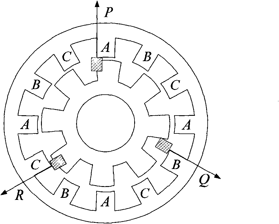
[0031] figure 1 Schematic for a conventional position sensor setup. The position sensor is usually integrated with the motor, and its main function is to provide the position information of the rotor relative to the stator. This information is the basis of the digital control of the motor. After the controller integrates various control strategies, it forms the driving signal of the power converter, thus determining the conduction Phase, and calculate the real-time speed of the motor. There are various t...


PUM


Abstract

The invention discloses a control method applicable for a high speed switched reluctance motor position-less sensor, belonging to the technical field of switched reluctance motor control. The invention, according to the characteristics of the switched reluctance motor, simplifies the rotor position detection into detection of commutation position. A fuzzy model of the non-linear relation with respect to the magnetic flux linkage (reference magnetic flux linkage) of the commutation position and the magnetic flux linkage of the alignment position of the stator and the rotor is established, so that the reference magnetic flux linkage at the reasonable commutation position thetah given at will and selected by comprehensively considering torque and output efficiency can be obtained only by storing the magnetic flux linkage-current feature curve of the alignment position of the stator and the rotor. By comparing the magnetic flux linkage detected in real time with the reference magnetic flux linkage, a corresponding commutation signal can be obtained. The invention not only has the advantages small required internal memory, simple and rapid algorithm, no need of hardware addition and the like, but also can optimally select the reasonable commutation position according to the features of the motor running, thus being very suitable for position detection during high speed running.

Description

technical field [0001] The invention relates to a position sensorless control method for a high-speed switched reluctance motor, which belongs to the technical field of switched reluctance motor control. Background technique [0002] The switched reluctance motor (SRM) has the characteristics of simple and solid structure, low cost, reliable operation, flexible control, high operating efficiency, and strong fault tolerance, and has unique application advantages in some special application fields. In military applications such as civil, industrial and aerospace applications, it has gradually received widespread attention and has a bright application prospect. [0003] The position detection link is one of the important components of the switched reluctance motor speed control system (SRD). The traditional position detection method is to obtain the rotor position information by installing a position sensor, mainly using photoelectric, electromagnetic, magnetic sensitivity and...

Claims


Application Information

Patent Timeline
IPC IPC(8): H02P6/18G01D5/14
Inventor 蔡骏邓智泉刘泽远曹鑫毛宇阳
Owner NANJING UNIV OF AERONAUTICS & ASTRONAUTICS
Why Eureka
Try Eureka