Method for realizing passive oriented buoy digital de-multiplexer

A technology of a demultiplexer and an implementation method, which is applied in the direction of digital technology network, multiplexing communication, orthogonal multiplexing system, etc., can solve the problems such as the principle that demultiplexing cannot be formed, and achieves simplified hardware design. , The effect of reducing raw material cost and improving reliability

Active Publication Date: 2012-11-07
THE 715TH RES INST OF CHINA SHIPBUILDING IND CORP
View PDF3 Cites 0 Cited by
  • Summary
  • Abstract
  • Description
  • Claims
  • Application Information

AI Technical Summary

Problems solved by technology

[0006] US Patent 4,979,694 (Gibert R.Grado.Difar demultiplexer circuit[P].United States Patent Number: 4,879,694 Nov.7, 1989) introduces a partial and specific demultiplexer circuit, but cannot form a clear demultiplexer circuit principle

Method used


Image

  • Method for realizing passive oriented buoy digital de-multiplexer
  • Method for realizing passive oriented buoy digital de-multiplexer
  • Method for realizing passive oriented buoy digital de-multiplexer

Examples


Embodiment Construction

[0027] Below in conjunction with accompanying drawing and embodiment the invention will be further described:

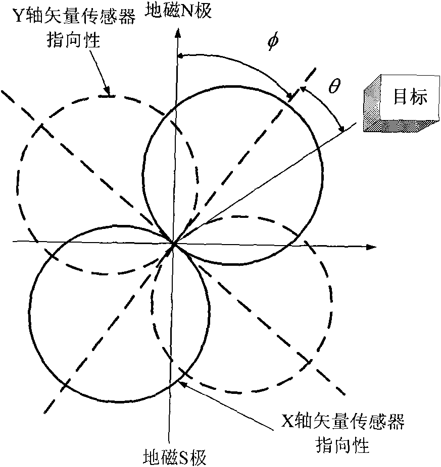
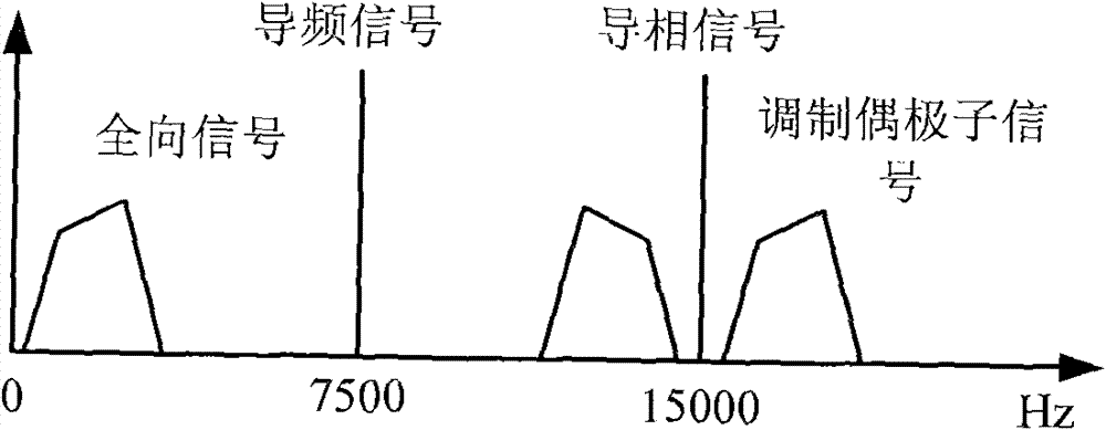
[0028] The invention is used for processing the composite signal output by the passive directional buoy. Before introducing the specific implementation of the demultiplexer, it is necessary to understand the knowledge of passive directional buoys and their composite signals. The combined vector sensor contained in the passive directional sonobuoy (DIFAR) is composed of an omnidirectional sound pressure hydrophone and two mutually orthogonal dipole sound velocity sensors. Since the direction of the buoy in the water is random, it also contains a compass to sense its own direction. The buoy will also rotate in the water, and the compass is required to correct the target orientation detected by the sensor. Following the format of the directional buoy, viewed from the top of the vector sensor, the two dipole sensors are along the X-axis direction and the Y-axis directi...


PUM


Abstract

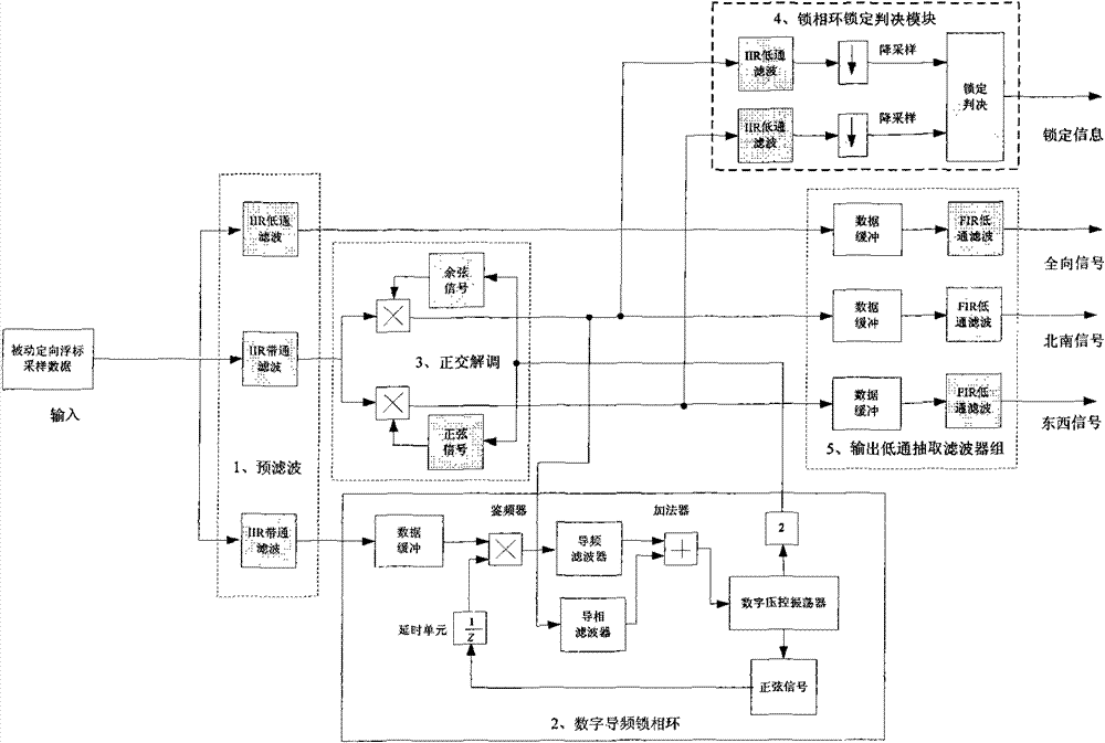
The invention relates to a method for realizing a passive oriented buoy digital de-multiplexer. The input is passive oriented buoy composite signal undergoing A / D sampling and digital discretization, and the output is omnidirectional signal, east-west signal, north-south signal and locking state signal undergoing the digital discretization. The method comprises the following steps of: firstly, digitally filtering the composite signal to separate the omnidirectional signal, the dipole quadrature modulation signal and the pilot frequency signal, wherein the frequency of the pilot frequency signal is tracked and locked by a pilot frequency phase locked loop so as to further track and lock the phase of the pilot phase signal, provide the sinusoidal and cosine signals with the same frequency and phase, and demodulate the dipole signal undergoing quadrature modulation; further performing the lowpass filtering, outputting the omnidirectional signal, the east-west signal and the north-south signal; and locking the information whether the output value given by a judging module is valid. The method has the advantages of reducing the complexity of a buoy receiver, simplifying the hardware design, eliminating the influence of simulated elements, ensuring the balance of two dipole symmetrical channels and improving reliability and oriented precision.

Description

Technical field [0001] The invention belongs to the intersection field of digital signal processing and sonobuoy, and mainly relates to a method for realizing a digital demultiplexer of a passive directional buoy. Background technique [0002] A passive directional buoy is an ocean monitoring instrument that not only listens to sounds in the ocean, but also determines the direction of the sound. It contains a combined sound vector sensor and a compass, and the buoy circuit combines the actual four-way signal into one composite audio signal and transmits it to the receiver through a radio link. The composite signal is demultiplexed at the receiving end for the acoustic signal processor to perform beamforming, time-frequency analysis and other processing. Correct demultiplexing is related to the orientation of the sound source, so the demultiplexer is a critical link in the buoy system. [0003] The demultiplexer of the previous passive directional buoy receiver is realized ...

Claims


Application Information

Patent Timeline
Patent Type & Authority Patents(China)
IPC IPC(8): H04L27/22H03D3/00H04J11/00H03L7/08H03H17/02
Inventor 王森赵海潮马晓民孟洪陈立新凌震莹
Owner THE 715TH RES INST OF CHINA SHIPBUILDING IND CORP
Why Eureka
Try Eureka