Small cylinder stretching device

A stretching device, a small technology, applied in the field of forming and manufacturing, can solve the problems of high cost, low qualification rate, difficult processing, etc., and achieve the effects of low cost, easy operation and small volume

Inactive Publication Date: 2009-12-23
HUBEI SANJIANG AEROSPACE HONGFENG CONTROL
View PDF0 Cites 1 Cited by
  • Summary
  • Abstract
  • Description
  • Claims
  • Application Information

AI Technical Summary

Problems solved by technology

[0004] 1. The design of the stretching die is used, and the processing is carried out by one or more stretches, and finally the end surface is leveled. The stretching die is large in size, high in cost, and has a long production cycle
[0005] 2. The processing is completed by mechanical processing, which has high cost. Due to the thin wall of the processed finished product, the processing is difficult and the pass rate is low.
[0006] 3. When the product is in the development stage, the number of parts is small, and the design state is often unstable. The cost of using the above two methods is too high, the production cycle is too long, and it is not suitable for the needs of market economic development.

Method used


Image

  • Small cylinder stretching device
  • Small cylinder stretching device
  • Small cylinder stretching device

Examples


Embodiment 1

[0037] First, process each component required in this embodiment:

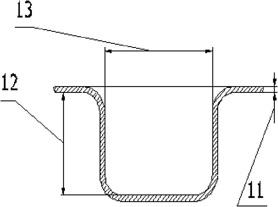
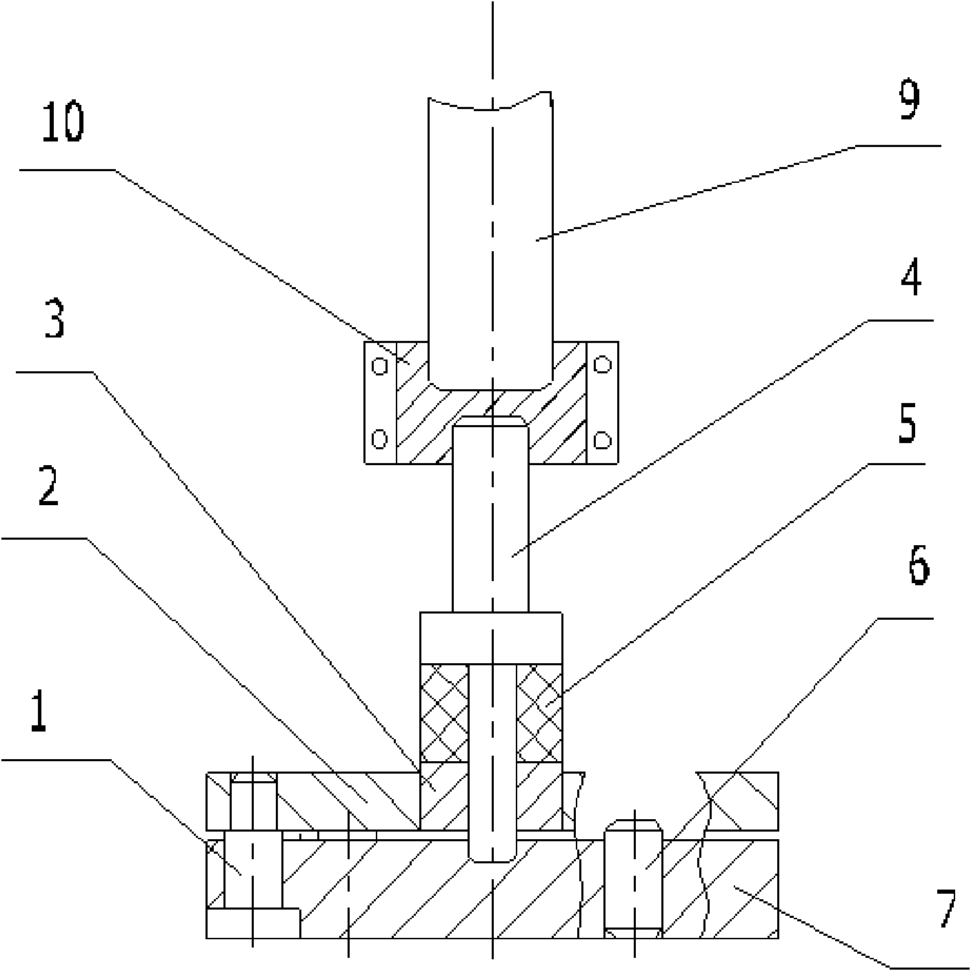
[0038] Making the stretching punch rod 4: design the outer surface of the head of the stretching punch rod 4 according to the required stretched shape structure of the stretched part 8; the handle of the stretching punch rod 4 is the force end, Used to withstand the pressure exerted by external forces;

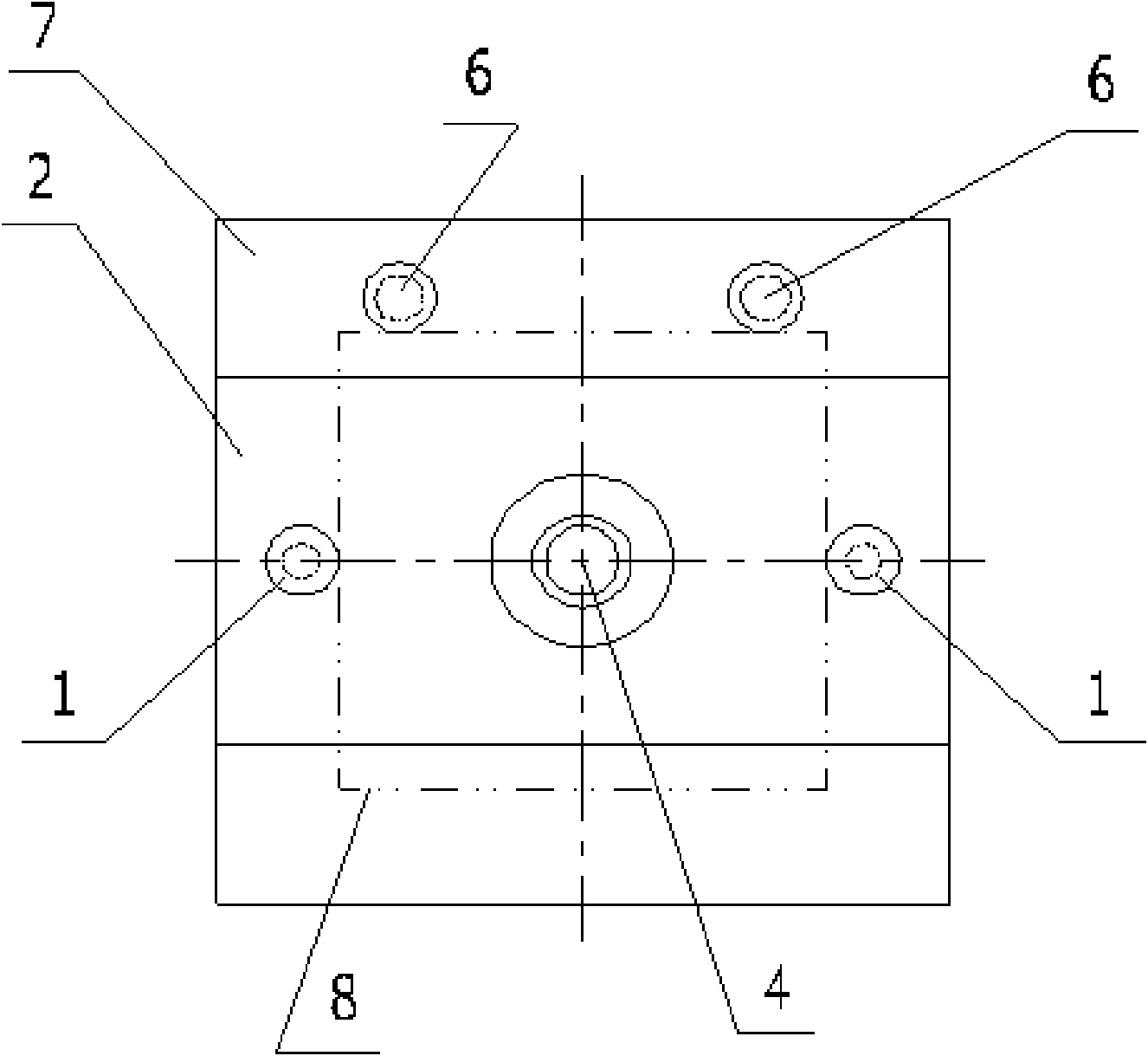
[0039]Make the positioning guide plate 2 and the concave template 7: set the positioning guide opening on the positioning guide plate 2, the diameter of the positioning guide opening is greater than the head outer diameter of the stretching punch rod 4, preferably the head of the stretching punch rod 4 The part can be matched with the positioning guide opening of the positioning guide plate 2; a cavity is provided on the concave template 7, and the structure of the cavity is matched with the structure of the outer surface of the head of the stretching punch rod 4, and the concave template 7 is installed on the...

Embodiment 2

[0045] In this embodiment, a pre-tightening structure is added on the basis of the first embodiment. In this embodiment, the positioning block 3 and the pre-tightening pad 5 are used to form a pre-tightening structure, so that the parts to be stretched can be solved during the stretching process. Go over the wrinkle problem.

[0046] First, improve the processing of the existing components in the first embodiment: on the basis of the processing described in the first embodiment, the stretching punch rod 4 is provided with a bump between the head and the shank. The shape of the block is preferably ring-shaped; the positioning guide plate 2 is processed so that it can fit with the positioning block 3 clearances.

[0047] Next, process the newly added pre-tightening structure: 1. Set up a positioning hole on the positioning block 3. The aperture of the positioning hole is larger than the outer diameter of the head of the stretching punch rod 4. The positioning block 3 needs to be...


PUM

PropertyMeasurementUnit
diameteraaaaaaaaaa
depthaaaaaaaaaa
thicknessaaaaaaaaaa

Abstract

The invention relates to the field of forming manufacture, and discloses a small cylinder stretching device comprising an stretching convex die rod, a concave die plate and a positioning guide plate, wherein the outer surface of the head of the stretching convex die rod is identical with the contour structure of the part to be stretched; a handle of the stretching convex die rod is a stress part and is used for bearing the pressure exerted by external force to the stretching convex die rod; the positioning guide plate is provided with a positioning guide port which has the diameter of larger than the outer diameter of the head of the stretching convex die rod; the concave die plate is provided with a cavity sleeved with the outer surface structure of the head of the stretching convex die rod; the concave die plate is arranged at the lower end of the guide plate; the cavity of the concave die plate is aligned with the positioning guide port of the guide plate; the head of the stretching convex die rod passes through the positioning guide port and applies force to the part to be stretched between the concave die plate and the positioning guide late. The stretching device is applicable to stretching forming manufacture of small cylinders of various materials, is characterized by being light, delicate and small, having low cost and convenient use and being capable of shortening the production cycle, and can be widely applied in manufacturing similar products of various types.

Description

technical field [0001] The invention relates to the field of molding manufacturing. Background technique [0002] In the process of product development, we often encounter a product with a small cylindrical structure. For example, the battery contacts in the battery installation box of the product are generally made of thin materials such as phosphor bronze QSn6.5-0.1, which need to be processed into a cylindrical structure with a small diameter and a shallow depth. For example, a cylindrical structure with a diameter of Φ5mm and a depth of 5.3(5+0.3)mm needs to be processed, and its wall thickness is 0.3mm. In the traditional industry, there are usually two methods for the manufacture of such products: one is to design a stretching die, use one or more stretches, and finally level the end surface to complete; the other is to use mechanical processing to complete the process. [0003] The prior art has the following problems in practical application: [0004] 1. The desig...

Claims


Application Information

Patent Timeline
Patent Type & Authority Applications(China)
IPC IPC(8): B21D22/20B21D37/10B21D37/12
Inventor 吴俊
Owner HUBEI SANJIANG AEROSPACE HONGFENG CONTROL
Why Eureka
Try Eureka