Novel conductive roller device

A technology of a conductive roller and a pressing roller device is applied in the surface treatment of metal sheets and strips, and in the field of electroplating tin, which can solve the problems of shortened bearing life, reduced production efficiency, affected lubrication effect, etc., to avoid induced current, improve service life, Avoid the effect of equipment heating

Inactive Publication Date: 2009-12-23
BEIJING STAR RIVER INTEGRATED EQUIP TECH
View PDF0 Cites 5 Cited by
  • Summary
  • Abstract
  • Description
  • Claims
  • Application Information

AI Technical Summary

Problems solved by technology

Its craftsmanship is attached Figure 4 The reflow section is composed of a grounding roller 16, a choke coil 17, a conductive roller 18, a quenching tank 19, a sinking roller 20, pure water 21, a steering roller 22, and a steering roller 23. The part of the strip steel in the middle of the two conductive rollers is used as a resistor The current is connected to the two conductive rollers, but when the alternating current is applied, the conductive rollers will generate heat due to electromagnetic induction, especially at the bearing seat and bearing. The induction heating will cause the temperature of the bearing seat and bearing to rise, and the temperature rise will The failure of the lubricating fluid will affect the lubrication effect, which will cause the temperature of the bearing to rise, the bearing will fail, the life of the bearing will be shortened, and the bearing will even be damaged in a short time, thereby increasing the number of maintenance times and maintenance costs, shortening the production time, and causing High cost and low production efficiency

Method used


Image

  • Novel conductive roller device
  • Novel conductive roller device
  • Novel conductive roller device

Examples


Embodiment Construction

[0012] in the attached Figure 4 In the figure, is the process flow diagram of the reflow section. After cleaning, tinning and hot air blowing, the strip steel passes through the reflow section. The strip steel is used as a resistor between the two conductive rollers 18. After the two conductive rollers are energized, they are heated and grounded. There is a choke coil 17 between the roller 16 and the conductive roller 18. Because the conductive roller 18 has a leakage current, the choke coil is used to generate a reverse induced electromotive force after passing through the alternating current to prevent the current from flowing out and reduce the leakage current through the grounding roller 16. Reduce energy consumption. Heat the tin on the surface of the steel plate to the melting point, and it is in a molten state, and the combination of tin and iron on the surface of the strip steel forms FeSn 2 After the steel strip passes through the water quenching tank 19, it is quenc...


PUM


Abstract

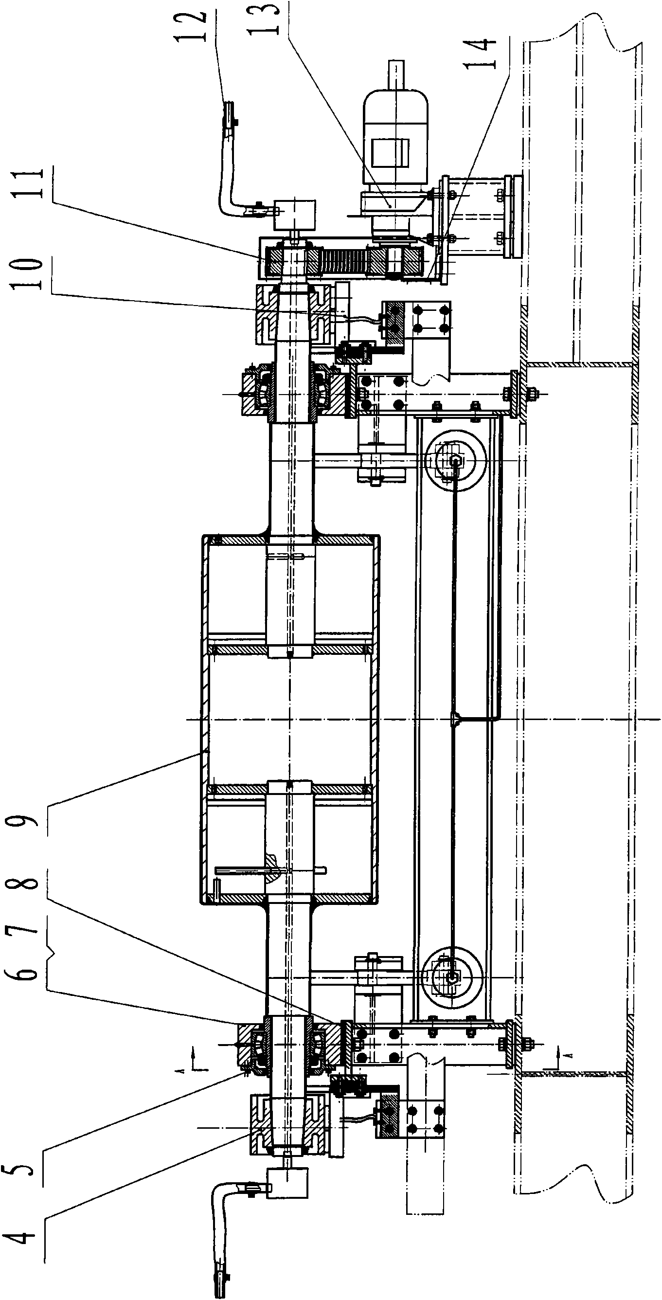
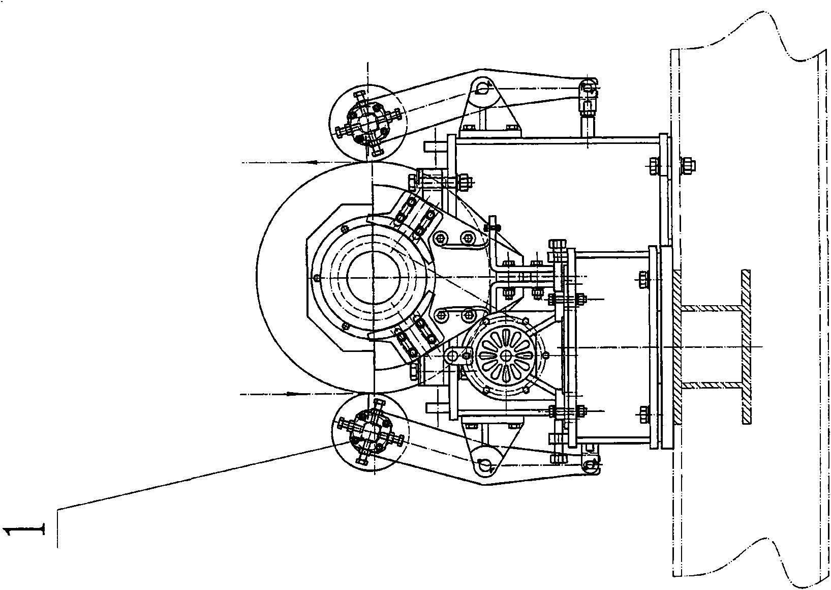
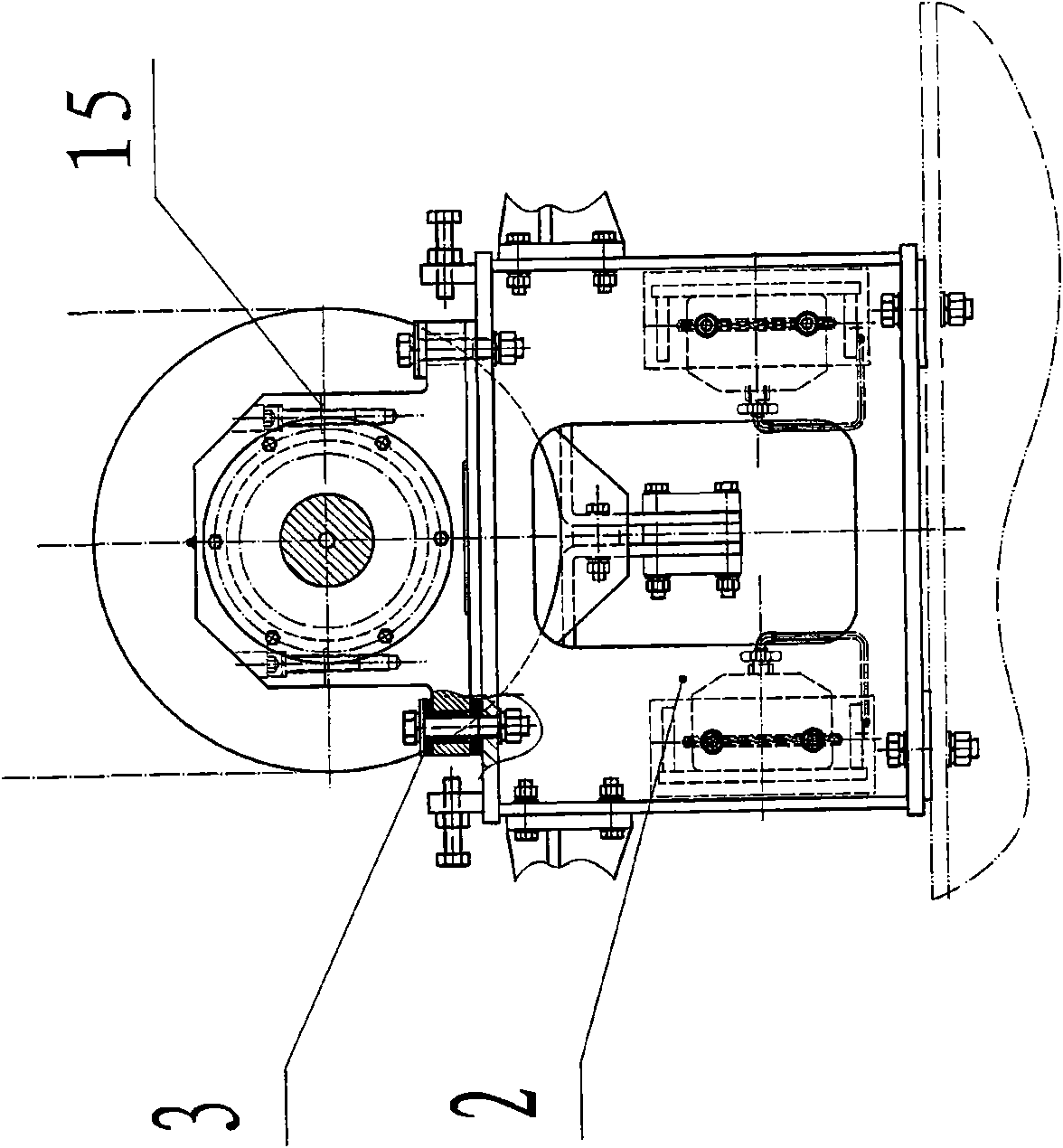
The invention provides a novel conductive roller device which aims at overcoming the defect that when a conductive roller of a soft-melting section of electrotinning is energized with AC, the conductive roller emits heat due to electromagnetism induction phenomenon; the novel conductive roller device is adopted especially at the position of a bearing seat or a bearing; pressing roll devices 1 are installed at the two sides of a stander 2, electricity collecting rings 4 are arranged at the two ends of the conductive roller; a bearing end cover 5, the bearing seat, the conductive roller 9 and a carbon brush device 10 are positioned at the lower side of the electricity collecting rings 4; the bearing seat comprises an upper part and a lower part which are an upper bearing seat 6 and a lower bearing seat 7 that are separated from each other by an insulation board, the material of which has magnetic insulation property; furthermore, the bearing seat is made of the material with the magnetic insulation property, and the bearing is also formed by the material with the magnetic insulation property; the bearing end cover 5 is made of the material with the magnetic insulation property, so that a ring-shaped magnetic field is avoided being formed, and the heat emitting phenomenon is prevented, thus greatly improving the working condition of the bearing, increasing the production efficiency, and saving the time and the production cost.

Description

technical field [0001] The invention belongs to the field of surface treatment of metal strips, especially the field of tin plating. Background technique [0002] Reflow is an important process in the continuous tinning production of strip steel. Its function is to heat the tinned strip steel to the melting point of tin above 232°C, so that the tin layer on the surface of the strip steel melts and flows and produces a metallic luster, and then the strip steel strip Immediately immersed in water, it becomes bright tinplate. During the reflow process, part of the tin reacts with the steel strip to form a tin-iron alloy layer, which can improve the corrosion resistance of the tinplate and the adhesion of the tin layer to the steel strip. At present, when tinning metal sheets and strips at home and abroad, the reflow section uses resistance heating or induction heating to heat the steel strip. In the continuous tinning production of strip steel, resistance reflow equipment is m...

Claims


Application Information

Patent Timeline
Patent Type & Authority Applications(China)
IPC IPC(8): C25D5/50C25D7/06
Inventor 汪为健尚东艳
Owner BEIJING STAR RIVER INTEGRATED EQUIP TECH
Why Eureka
Try Eureka