Grouping synchronization type optical fiber sensing analyzer

An optical fiber sensing and packet synchronization technology, which is applied in the physical field and can solve the problems of lack of diagnostic analysis capabilities and inability to access multiple types of optical fiber sensors at the same time.

Inactive Publication Date: 2009-12-23
上海前所光电科技有限公司
View PDF0 Cites 23 Cited by
  • Summary
  • Abstract
  • Description
  • Claims
  • Application Information

AI Technical Summary

Problems solved by technology

[0007] The purpose of the present invention is to provide a packet synchronous optical fiber sensor analyzer, which solves the problem that the optical fiber sensor analyzer signal acquisition channels in the prior art are limited and cannot be connected at the same time. Many types of fiber optic sensors are introduced, and the technical problems of lack of diagnostic and analysis capabilities

Method used


Image

  • Grouping synchronization type optical fiber sensing analyzer
  • Grouping synchronization type optical fiber sensing analyzer
  • Grouping synchronization type optical fiber sensing analyzer

Examples


Embodiment Construction

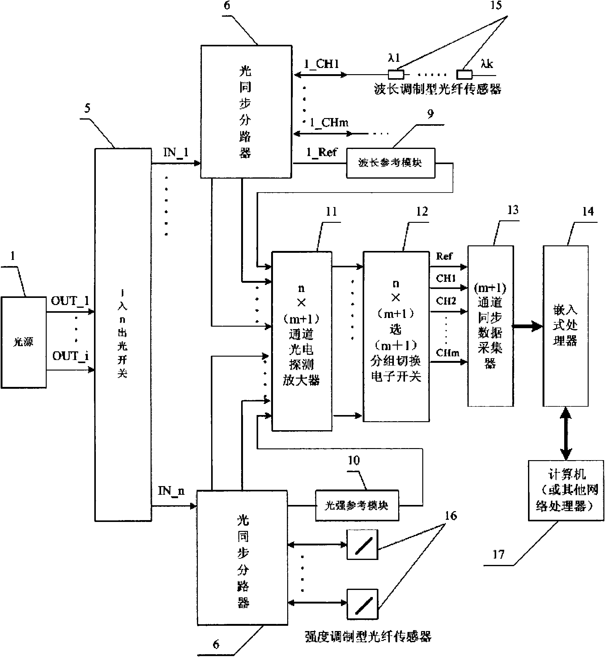
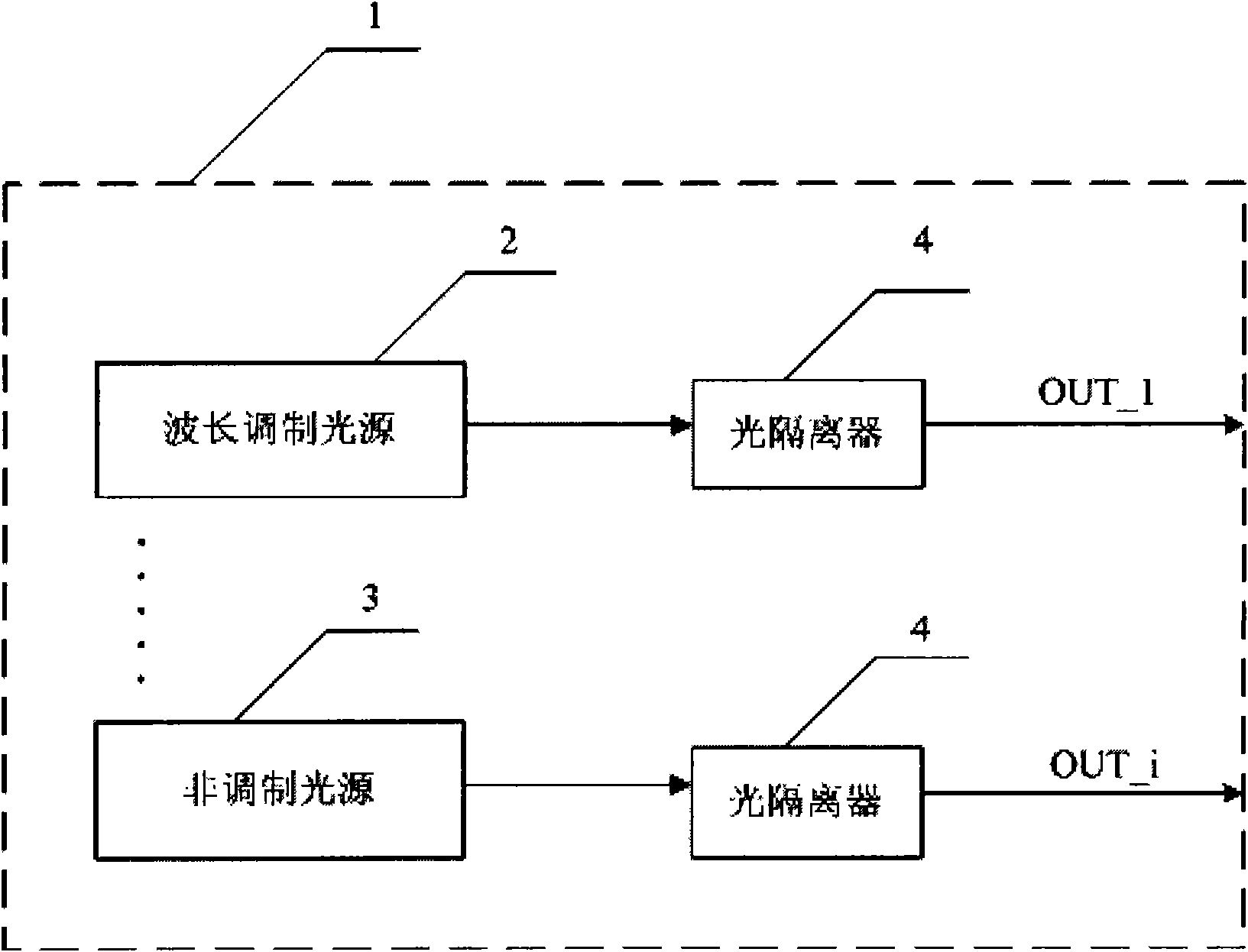
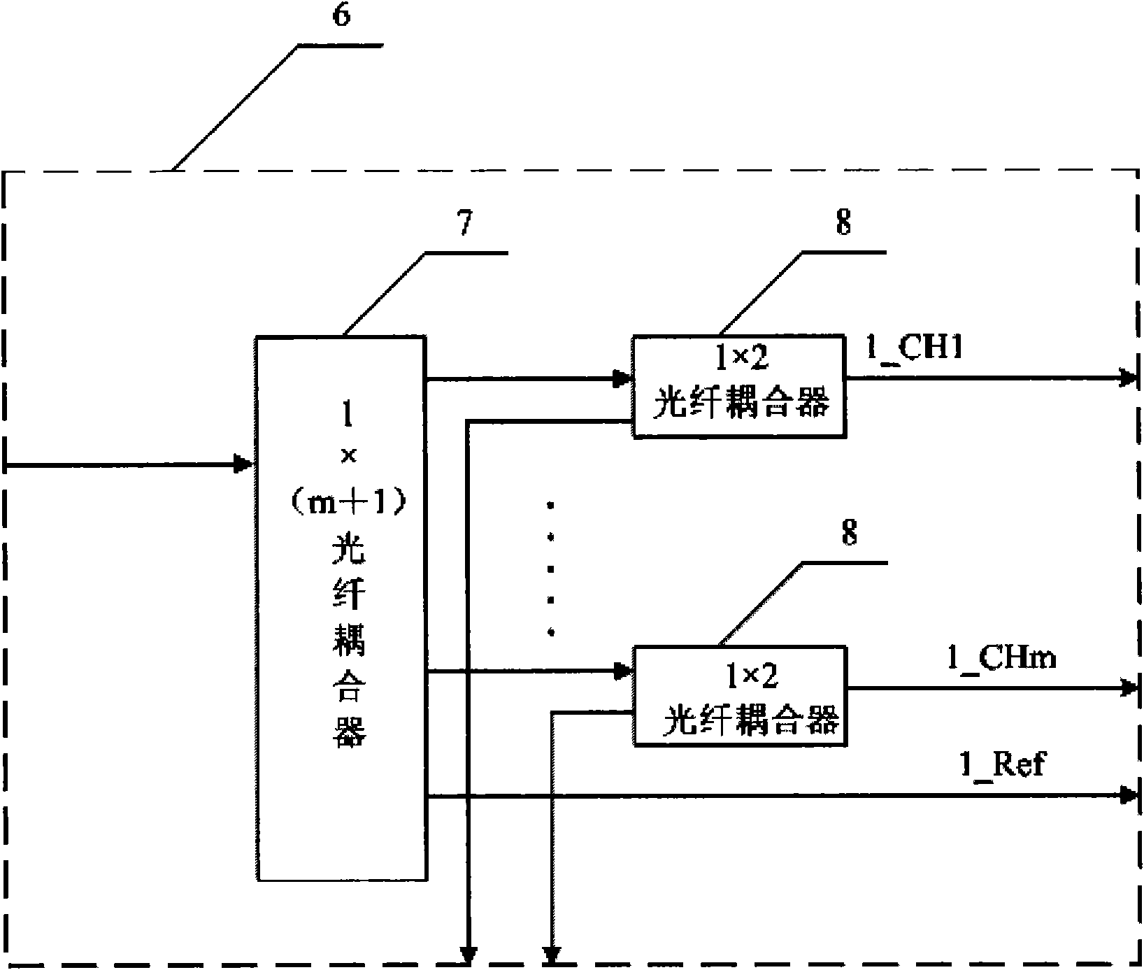
[0024] Such as figure 1 , figure 2 , image 3 and Figure 4 As shown, the meanings of the symbols in the figure are: 1 represents the light source, 2 represents the wavelength modulation light source, 3 represents the non-modulation light source, 4 represents the optical isolator, and 5 represents the i-in and n-out type optical switch (i=1, 2, ... 24 ; n=1, 2, ... 24), 6 means optical synchronous splitter, 7 means 1×(m+1) fiber coupler, 8 means 1×2 fiber coupler, 9 means wavelength reference module (Etalon) , 10 represents the light intensity reference module (optical power monitoring), 11 represents the n×(m+1) channel photoelectric detection amplifier, 12 represents the n×(m+1) selection (m+1) group switching electronic switch, and 13 represents ( m+1) channel synchronous data collector, 14 represents an embedded processor, 15 represents a wavelength type optical fiber sensor, 16 represents an intensity type optical fiber sensor, and 17 represents a computer.

[0025] ...


PUM


Abstract

The invention discloses a grouping synchronization type optical fiber sensing analyzer, which consists of a light source, an optical switch, optical synchronous splitters, a wavelength reference module, a light intensity reference module, a photoelectric detection amplifier, a multi-channel synchronous data acquisition unit and an embedded processor. Optical signals of the light source are orderly switched to a plurality of optical synchronous splitters through the optical switch; each optical synchronous splitter is connected with the reference modules and a group of optical fiber sensors; the optical fiber sensors convert incident light into optical signals representing physical quantity to be detected, and output the optical signals to the photoelectric detection amplifier; the photoelectric detection amplifier converts the optical signals which are respectively output by the optical fiber sensors and the reference modules into voltage signals; the voltage signals are switched by a grouping switching electronic switch, and then access the multi-channel synchronous data acquisition unit to complete analog digital conversion; digital signals after the analog digital conversion are calculated by the embedded processor into an actually measure value; and the embedded processor controls the synchronous switching of the optical switch and the grouping switching switch so as to realize the grouping synchronization type analysis and demodulation of large-scale optical fiber sensors.

Description

Technical field: [0001] The invention relates to the field of physics, in particular to optical sensing technology, in particular to a packet synchronous optical fiber sensing analyzer. Background technique: [0002] With the development and maturity of dense wavelength division multiplexing DWDM technology, erbium-doped fiber amplifier EDFA technology and optical time division multiplexing OTDM technology, optical fiber communication technology is developing in the direction of ultra-high-speed and large-capacity communication systems, and is gradually evolving into an all-optical network. . Among them, fiber optic sensors have been widely used because of their huge technical advantages in anti-electromagnetic interference, light weight, sensitivity, and long-distance transmission. [0003] Fiber Bragg grating sensing technology and fiber microelectromechanical (MEMS) sensing technology are two typical fiber sensor technologies. [0004] Fiber Bragg grating sensing techno...

Claims


Application Information

Patent Timeline
Patent Type & Authority Applications(China)
IPC IPC(8): G01D5/353G02B6/26
Inventor 钟少龙吴亚明
Owner 上海前所光电科技有限公司
Why Eureka
Try Eureka