
Converter for low-voltage traversing double-fed wind driven generator

A wind turbine and low-voltage ride-through technology, which is applied in the field of wind turbine converters and doubly-fed wind generator converters, can solve the problems of long operation period, increased protection measures, and increased equipment costs.

Inactive Publication Date: 2009-12-23
BEIJING LEADER & HARVEST ELECTRIC TECH
View PDF0 Cites 17 Cited by
  • Summary
  • Abstract
  • Description
  • Claims
  • Application Information

AI Technical Summary

Problems solved by technology

The rotor current bypass measures using thyristors have the following defects: On the one hand, thyristor devices cannot achieve controlled shutdown, so their action cycle is longer than that of full-control devices, which restricts the control effect of the entire doubly-fed induction wind turbine. Realization, even in the application, in order to avoid the thyristor being in the conduction state when the inverter is restarted, it is necessary to detect whether the current in the thyristor circuit is zero, which not only increases the complexity of the implementation of protection measures but also reduces the overall System Operational Reliability
On the other hand, the thyristor device has limited ability to withstand dv / dt, and needs more absorption circuits, thus increasing the power consumption of the equipment, increasing the cost of the equipment, and increasing the volume of the equipment

Method used


Image

  • Converter for low-voltage traversing double-fed wind driven generator
  • Converter for low-voltage traversing double-fed wind driven generator
  • Converter for low-voltage traversing double-fed wind driven generator

Examples


Embodiment Construction

[0026] The present invention will be further described below in conjunction with the accompanying drawings and embodiments.

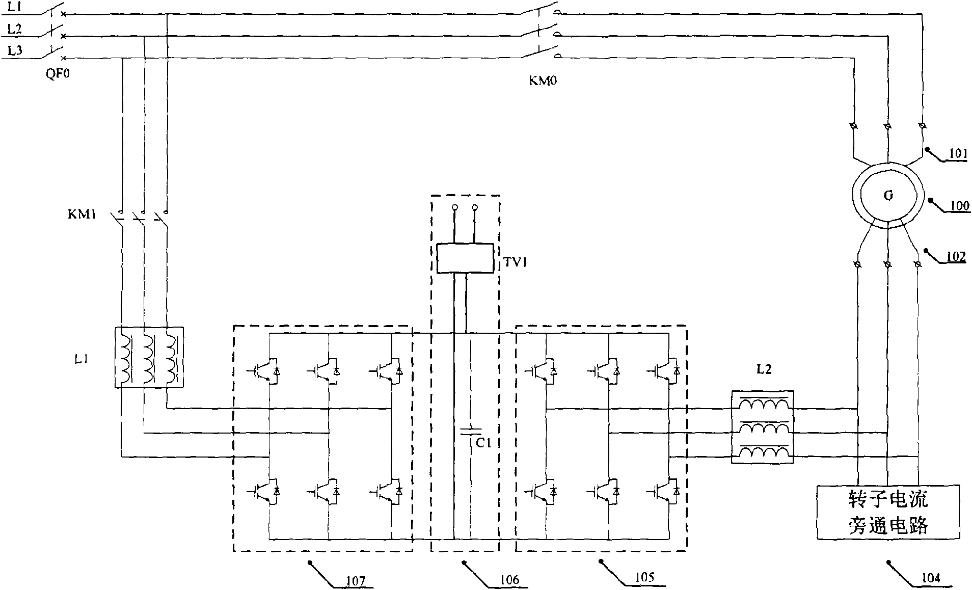
[0027] figure 1 It is a schematic diagram of a generator system composed of a low-voltage ride-through type doubly-fed wind power generator converter and a doubly-fed induction wind power generator of the present invention. As shown in the figure, the doubly-fed induction wind generator 100 is composed of a stator 101 and a rotor 102 . The low-voltage ride-through double-fed wind turbine converter includes: stator-side grid-connected switch KM0, rotor-side filter L2, rotor-side converter 105, intermediate DC link 106, grid-side converter 107, and grid-side rectification reactance L1, grid side grid switch KM1.

[0028] Wherein, the stator 101 is connected to the grid through the grid-connected switch KM0 on the stator side. The rotor 102 is sequentially connected to the power grid through the rotor-side filter L2, the rotor-side converter 105, the in...


PUM


Abstract

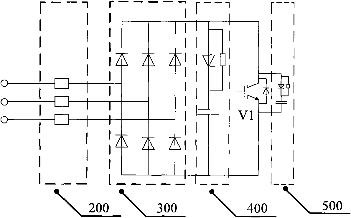
The invention provides a converter for a low-voltage traversing double-fed wind driven generator, which is characterized in that the middle direct-current link comprises a direct-current capacitor and a direct-current voltage detector; the direct-current voltage detector is connected in parallel at two ends of the direct-current capacitor to detect the voltage of the middle direct-current link; the converter is further provided with a rotor current bypass circuit; the rotor current bypass circuit is composed of a current limiting resistor, a three-phase non-control rectifier and a full-control component sequentially connected in series; the current limiting resistor end is used as an accessing end of the current bypass circuit and is connected in parallel between the rotor and the rotor side converter; and the direct-current voltage detector is in signal connection with the rotor current bypass circuit so as to control the switch of the full-control component. When the wind driven generator is in system fault, the voltage of the middle direct-current link is too high, the full-control component is electrified, bypassing or the rotor current is realized so that running of a grid-side converter of the double-fed sensing wind driven generator is kept continuous, which provides strongly help for failure recovery of the grid.

Description

technical field [0001] The invention relates to a wind power generator converter, in particular to a doubly-fed wind power generator converter with fast execution, simple control, reliable operation, low power consumption and strong low-voltage ride-through capability. It belongs to the technical field of wind power generation equipment. Background technique [0002] Now that the traditional energy is shrinking day by day, the world has set off an upsurge in the development of renewable resources. Among them, wind energy has become the leader with the most industrialized development conditions among new energy sources, and it is also the renewable clean energy with the most development potential in my country in the next few years. As of 2008, my country's total installed capacity of wind power reached 12.21 million kilowatts, accounting for 10% of the world's total installed capacity, ranking fourth in the world. In 2008 alone, my country's new installed capacity of wind ...

Claims


Application Information

Patent Timeline
IPC IPC(8): H02J3/38
CPCY02E10/763Y02E10/76
Inventor 宋海涛
Owner BEIJING LEADER & HARVEST ELECTRIC TECH
Learn More