

Special idle gear system for four-roller compact spinning machine
A bridge gear, spinning machine technology, applied in spinning machine, open-end spinning machine, continuous winding spinning machine, etc., can solve the problems of limited space of accumulation tube, high cost, and high cost of modification, Achieve the effect of low cost, reasonable structure and convenient disassembly and replacement
- Summary
- Abstract
- Description
- Claims
- Application Information
AI Technical Summary
Problems solved by technology
Method used
Image

Examples
Embodiment 1
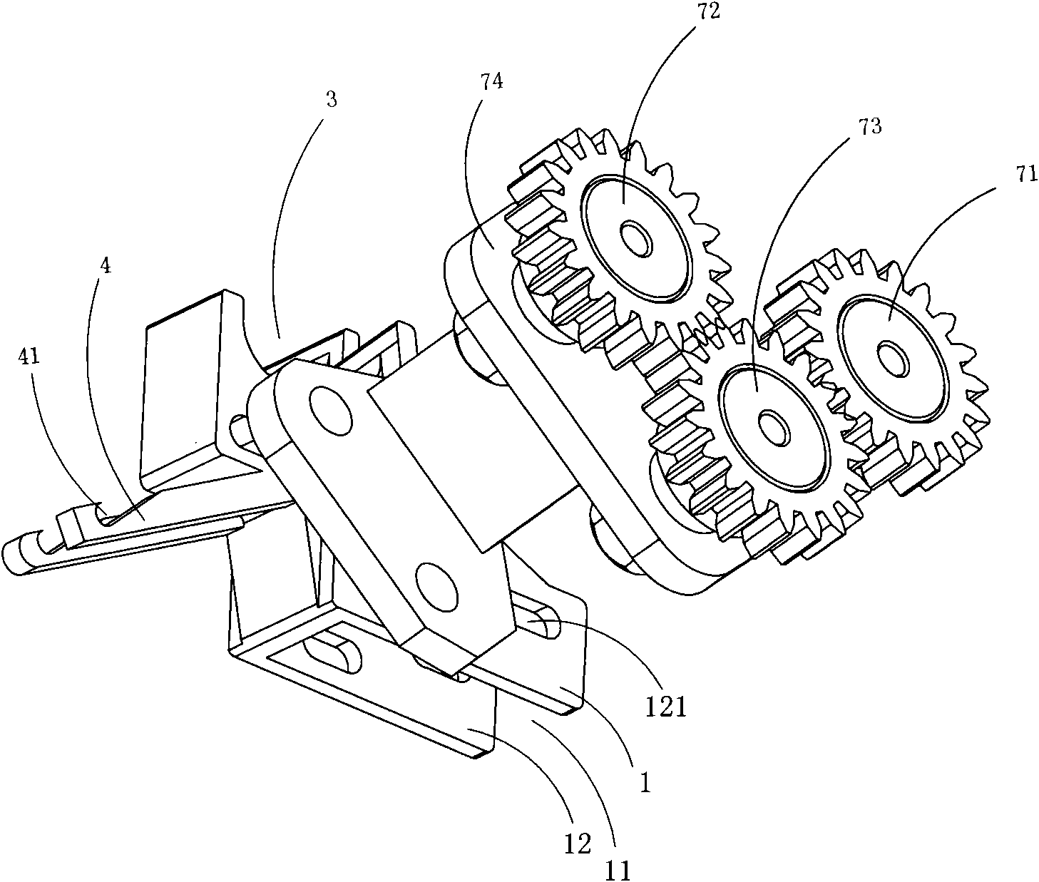
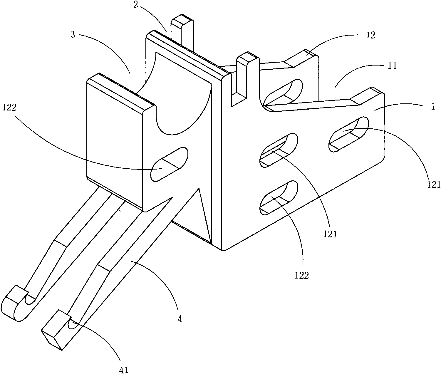
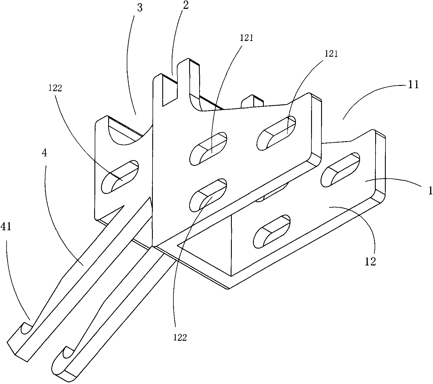
[0043] Figure 1 to Figure 6 A first embodiment of the invention is shown, in which figure 1 It is a schematic diagram of a three-dimensional structure of the first structure of the present invention; figure 2 yes figure 1 A schematic diagram of the three-dimensional structure of the support frame in the bridge gear device dedicated to the four-roller compact spinning machine shown; image 3 yes figure 2 A schematic diagram of the three-dimensional structure of the support frame when viewed from another angle; Figure 4 yes figure 2 A structural schematic diagram of the support frame shown when viewed from the side; Figure 5 yes figure 1 A schematic diagram of a three-dimensional structure of the bridge gear assembly in the bridge gear device shown; Image 6 yes Figure 5 A structural schematic diagram of the bridge gear assembly shown when viewed from the side.
[0044] This embodiment is a special bridge gear device for a four-roller compact spinning machine, se...
Embodiment 2
[0052] Figure 7 to Figure 13 Shows the second specific embodiment of the utility model, wherein, Figure 7 It is a schematic diagram of a three-dimensional structure of the second structure of the present invention; Figure 8 yes Figure 7 A schematic diagram of the three-dimensional structure of the support frame in the bridge gear device dedicated to the four-roller compact spinning machine shown; Figure 9 yes Figure 8 A schematic diagram of the three-dimensional structure of the support frame when viewed from another angle; Figure 10 yes Figure 8 A structural schematic diagram of the support frame shown when viewed from the side; Figure 11 Figure 7 A three-dimensional structural schematic diagram of the cotton suction flute installation part in the bridge gear device dedicated to the four-roller compact spinning machine shown; Figure 12 yes Figure 11 A schematic diagram of a three-dimensional structure of the suction flute mounting part shown when viewed fr...
Embodiment 3
[0056] Figure 14 to Figure 16 A third embodiment of the invention is shown, in which Figure 14 It is a three-dimensional structural schematic diagram of the support member and the installation base in the third structure of the present invention; Figure 15 yes Figure 14 A schematic diagram of a three-dimensional structure of the middle support; Figure 16 yes Figure 15 A schematic diagram of the structure of the support shown when viewed from the side.
[0057] This embodiment is basically the same as Embodiment 1, the difference is: see Figure 14 to Figure 16 , the structural shapes of the support member 8 and the installation base 74 are different. In this embodiment, the cotton-absorbing flute mounting part 4 is a boss protruding from the bottom of the supporting part 8, and a cotton-absorbing flute installation groove 41 is respectively provided on the left and right sides of it. The shape of the installation base 74 matches the shape of the support member 8 in...
PUM
 Abstract
Description
Claims
Application Information