
Electric fence exciter circuit and method for controlling stored energy capacity to charge

A technology for energy storage capacitors and exciters, which is applied in electric pulse generator circuits, electrical program control, and systems for storing electric energy, etc., can solve the problems of high cost, high voltage safety cost, accumulation, etc., and achieve low cost, circuit simple effect

Inactive Publication Date: 2012-10-10
李健雄
View PDF4 Cites 0 Cited by
  • Summary
  • Abstract
  • Description
  • Claims
  • Application Information

AI Technical Summary

Problems solved by technology

The use of resistance direct voltage division detection involves directly connecting the secondary end of the output pulse transformer with the ground of other control circuits of the exciter, which will make it difficult to achieve the withstand voltage safety requirements required in the IEC60335-2-76 or UL69 standards. It is very difficult and costly. At the same time, if the exciter is interconnected with other devices, such as PCs, it is easy to accumulate charges on other devices and damage the interconnected devices; and special pulse transformers or photoelectric isolation are used to isolate The detection method also involves the problem of high cost of withstand voltage safety required in the IEC60335-2-76 or UL69 standard

Method used


Image

  • Electric fence exciter circuit and method for controlling stored energy capacity to charge
  • Electric fence exciter circuit and method for controlling stored energy capacity to charge
  • Electric fence exciter circuit and method for controlling stored energy capacity to charge

Examples


Embodiment Construction

[0029] In order to describe the technical content, structural features, achieved goals and effects of the present invention in detail, the following will be described in detail in conjunction with the embodiments and accompanying drawings.

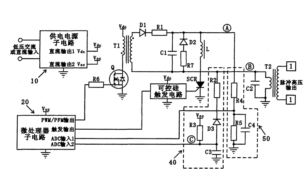
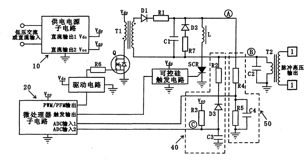
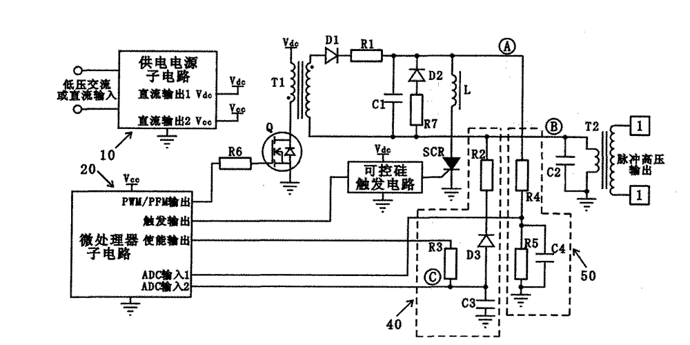
[0030] see figure 1, which is a schematic diagram of the main circuit structure of the present invention, including a power supply sub-circuit 10, and also includes a circuit capable of generating pulse current connected to the power supply; a microprocessor sub-circuit 20 is connected to the pulse current circuit, and Controlled by the microprocessor sub-circuit 20 . The pulse current circuit also includes a charging sub-circuit and a discharging sub-circuit. The charging sub-circuit includes a field effect transistor Q, a single-ended flyback transformer T1, a rectifier diode D1, a first resistor R1, and an energy storage capacitor C1; the primary terminal of the single-ended flyback transformer T1 is electrically connected to the power...


PUM


Abstract

The invention discloses an electric fence exciter circuit for detecting pulsed voltage of an electric fence and a method for controlling a stored energy capacity to charge; The electric fence exciter circuit is connected with a sub-circuit of a microprocessor which comprises software which controls the detection of the pulsed voltage of the electric fence and the stored energy capacity to charge;The sub-circuit of the microprocessor detects the state of all independent power supplies of sub-circuits of the power supply, simultaneously can control the stored energy capacity to charge, and thevoltage of the fence of the output end by detecting the negative peak value of voltage waveform of the input end of a pulsed output transformer through lookup a table; and the invention has simple circuit structure and low cost.

Description

technical field [0001] The invention relates to an electric fence exciter circuit for detecting electric fence pulse voltage and a method for controlling charging of an energy storage capacitor. Background technique [0002] Most of the modern electric fence actuators currently used in the field of security and animal husbandry are energy-limited actuators. The energy-limited exciter is to periodically charge the energy storage capacitor in the exciter, and then discharge the energy storage capacitor through the output pulse transformer, and generate pulse high voltage on the secondary side of the output pulse transformer. [0003] Most of the electric fence exciters used in the field of animal husbandry are open-loop operation, and usually do not need to detect their fence pulse voltage, but a few high-performance electric fence exciters for agriculture and animal husbandry have the ability to detect their output electric fence pulse voltage and display the function of its...

Claims


Application Information

Patent Timeline
Patent Type & Authority Patents(China)
IPC IPC(8): G01R19/04H03K3/02G05B19/04H02J15/00
Inventor 李健雄
Owner 李健雄
Learn More