Single battery control system of vehicular power supply

A single battery, vehicle power supply technology, applied in general control systems, control/regulation systems, computer control, etc., can solve the problems of accelerated battery damage, internal resistance, terminal voltage, capacity inconsistency, and reduced battery pack usage levels. Achieve the effect of extending service life, improving overall performance and improving reliability

A single battery, vehicle power supply technology, applied in general control systems, control/regulation systems, computer control, etc., can solve the problems of accelerated battery damage, internal resistance, terminal voltage, capacity inconsistency, and reduced battery pack usage levels. Achieve the effect of extending service life, improving overall performance and improving reliability

CN101615809AInactive Publication Date: 2009-12-30ENN SCI & TECH DEV

Image

  • Single battery control system of vehicular power supply
  • Single battery control system of vehicular power supply
  • Single battery control system of vehicular power supply

Examples


Embodiment 1

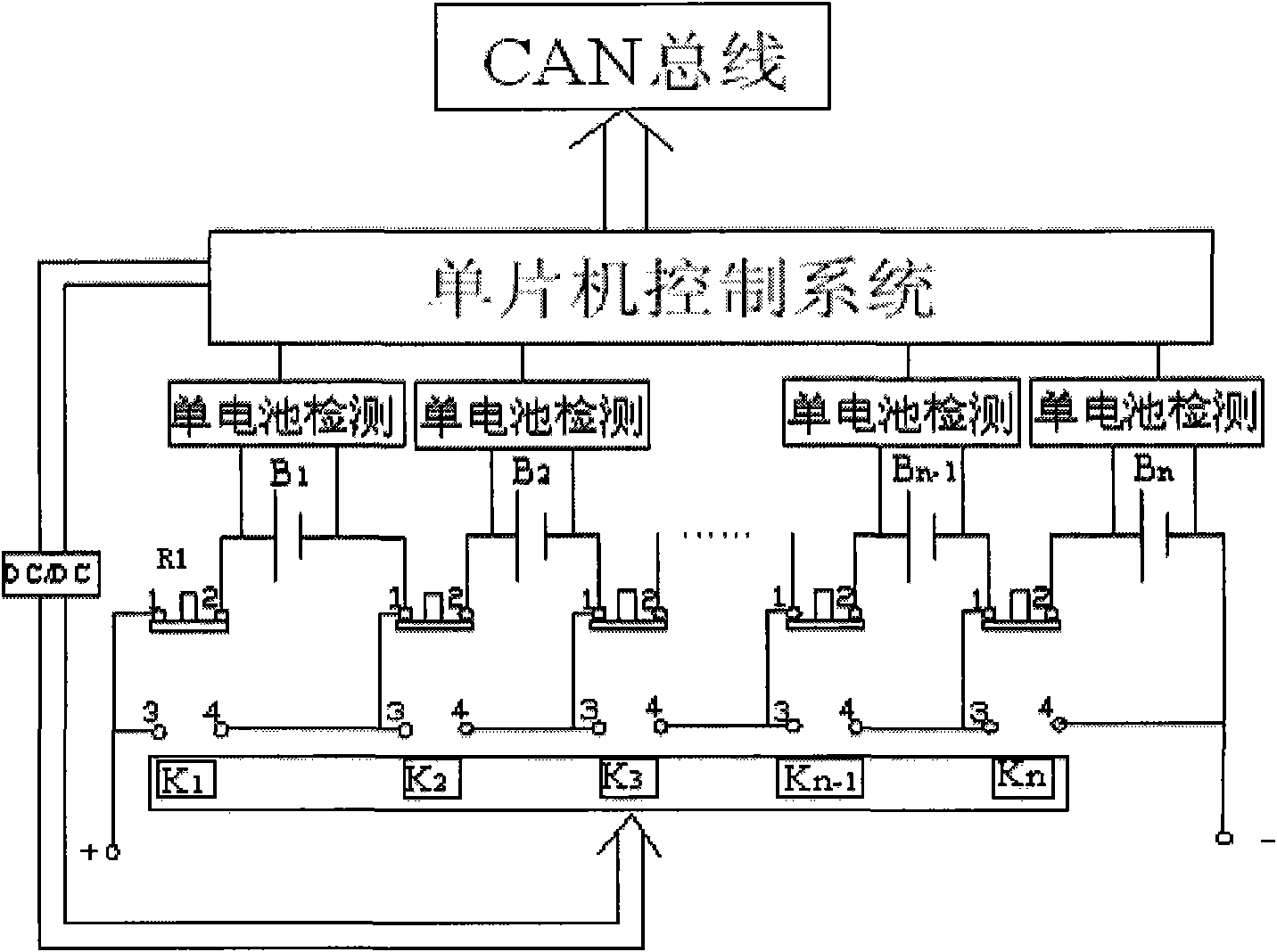
[0028] This solution is applied to hybrid or pure electric vehicles. In order to realize the detection and protection of single batteries in the power management system, a single-pole, double-set relay is added in front of each battery connected in series. figure 1 Cell B shown in 1 Front relay R 1 For example, R 1 It is a normally closed relay, and its position is connected to contacts 1 and 2 under normal conditions. If battery B is in the process of charging and discharging the battery pack 1 Overshoot or overdischarge occurs, R 1 The action makes the contacts 1 and 2 disconnected, and 3 and 4 are turned on, so that the single battery B 1 are protected by disconnection without affecting the B 1 Normal charging and discharging of other batteries connected in series.


PUM


Abstract

The invention provides a new thought about single battery control in vehicular power supply management and uses a novel method. The front end of a single battery of a series battery pack is provided with a single-pole double-throw relay. When a battery state detection part of the system detects that one single battery is in over-charge or over-discharge, the relay acts so that the single battery is open-circuit and exits a loop, and other normal batteries continue to work and are not influenced.

Description

technical field [0001] The invention belongs to the field of power management system control, in particular to a control system of a vehicle power supply battery. Background technique [0002] As a product of modern human civilization, automobiles not only bring convenience and comfort to human life, but also have an inescapable responsibility for the deterioration of the natural environment. Cars emit harmful gases into the atmosphere every year, accounting for more than 60% of the total air pollution. Today, with the continuous improvement of human life quality, the urgent need to save the natural environment on which human beings depend has posed a severe challenge to the development of the automobile industry. The emergence of gasoline-electric hybrid vehicles is gradually improving this situation. This kind of vehicle has two kinds of energy for starting. It combines the internal combustion engine, electric motor and battery pack with a certain capacity through an advan...

Claims


Application Information

Patent Timeline
30 Dec 2009
Publication
CN101615809A
IPC
H02J7/00; H02H7/18; G05B15/02
Inventors
张洪延; 陈红涛