Parallel resonance oscillation wave generation device

A technology for resonant oscillation and generating device, which is applied in the direction of testing dielectric strength, electrical components, testing circuits, etc., and can solve problems such as affecting the attenuation process of damped oscillatory waves.

Inactive Publication Date: 2009-12-30
薛建仁
View PDF1 Cites 11 Cited by
  • Summary
  • Abstract
  • Description
  • Claims
  • Application Information

AI Technical Summary

Problems solved by technology

[0003] In "An Oscillating Wave Generating Device for Electrical Equipment Test", it is proposed that the frequency modulation and voltage regulation power supply is used as the excitation, and after the resonant high voltage is generated through the LC series resonance, the LC series resonance circuit is closed with a low

Method used


Image

  • Parallel resonance oscillation wave generation device
  • Parallel resonance oscillation wave generation device
  • Parallel resonance oscillation wave generation device

Examples


Embodiment Construction

[0018] The accompanying drawings disclose the basic principles of the present invention and the implementation of specific examples thereof without limitation, and the present invention will be further described below in conjunction with the examples.

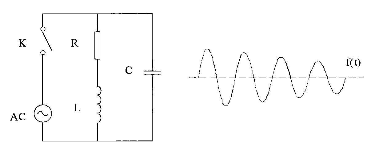
[0019] Depend on figure 1 It can be seen that the basic principle is: when K is closed, the AC excitation power supply AC provides an AC excitation voltage to the parallel circuit of the inductor L and capacitor C. When the output frequency of the excitation power supply AC is the same as the resonance frequency of the inductor L and capacitor C, LC Parallel loop resonance, adjust the output amplitude of the excitation power supply AC, after the resonance voltage of the LC parallel loop reaches a predetermined value, turn on K, cut off the excitation power supply, and because the inductance L has internal resistance R, the LC loop produces a damped oscillation wave f (t).

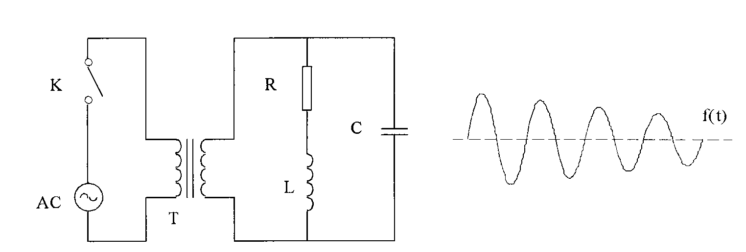
[0020] Depend on figure 2 It can be seen that an ex...


PUM


Abstract

The invention discloses a parallel resonance oscillation wave generation device. A frequency modulation and voltage regulation power supply AC, a capacitor C and an electric inductor L form a shunt circuit. The frequency of the power supply AC is adjusted to resonate with an LC circuit, then the output voltage of the power supply AC is adjusted to a preset value, the power supply AC is shutoff, and thus the damped oscillatory wave f(t) is produced on the LC circuit. During the concrete application, an exciting transformer T or a leakage inductance transformer TL is arranged between the power supply AC and the LC circuit, a primary side of the transformer is connected with the output of the power supply AC, and a secondary side of the transformer is parallelly connected with the LC circuit. When the leakage inductance transformer is adopted, a leakage inductor L of the secondary side of the leakage inductance transformer is parallelly connected with the capacitor C. The device has the advantages that the device can produce the oscillatory wave with the voltage of between 1 and 5,000kV on the LC circuit without the switching or shutoff of an electronic switch, and has broad application in sine wave withstand voltage and local discharge measurement of high-voltage equipment.

Description

technical field [0001] The invention relates to an oscillating wave generating device, in particular to a parallel resonant oscillating wave generating device which can be used in electric power tests. Background technique [0002] In the utility model patent No. ZL200820184923.7 "An Oscillatory Wave Generator for Electrical Equipment Test", the existing German SABA company's DC-excited oscillatory wave generator is clearly described, and the Disadvantages of DC excitation to generate damped oscillatory wave devices are described. [0003] In "An Oscillating Wave Generating Device for Electrical Equipment Test", it is proposed that the frequency modulation and voltage regulation power supply is used as the excitation, and after the resonant high voltage is generated through the LC series resonance, the LC series resonance circuit is closed with a low voltage electronic switch to generate damping Oscillating wave, during the process of the device generating the damped oscill...

Claims


Application Information

Patent Timeline
IPC IPC(8): H03B28/00G01R31/14
Inventor 薛建仁
Owner 薛建仁
Why Eureka
Try Eureka