Vibration suppressing method and device

A technology of vibration suppression and vibration acceleration, which is applied in the direction of manufacturing tools, metal processing machinery parts, maintenance and safety accessories, etc., to achieve accurate and stable speed, suppress tool wear, and improve quality

Active Publication Date: 2010-01-13
OKUMA CORP
View PDF3 Cites 32 Cited by
  • Summary
  • Abstract
  • Description
  • Claims
  • Application Information

AI Technical Summary

Problems solved by technology

However, in this vibration suppressing device, a calculation error occurs between the natural frequency calculated by the arithmetic unit and the actual natural frequency due to calculation formula errors. Assuming a situation where Flutter continues

Method used


Image

  • Vibration suppressing method and device
  • Vibration suppressing method and device
  • Vibration suppressing method and device

Examples


no. 1 approach

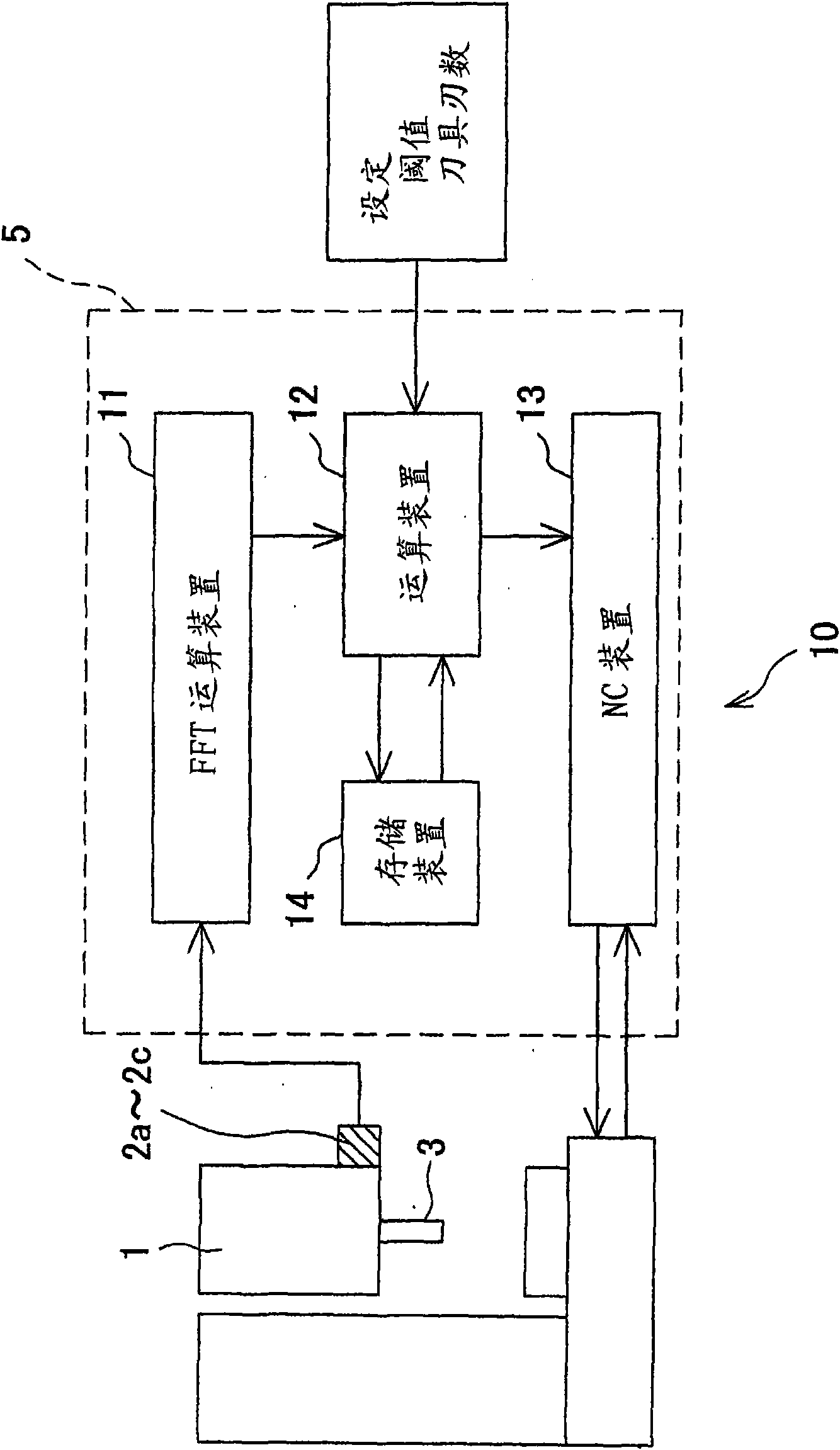
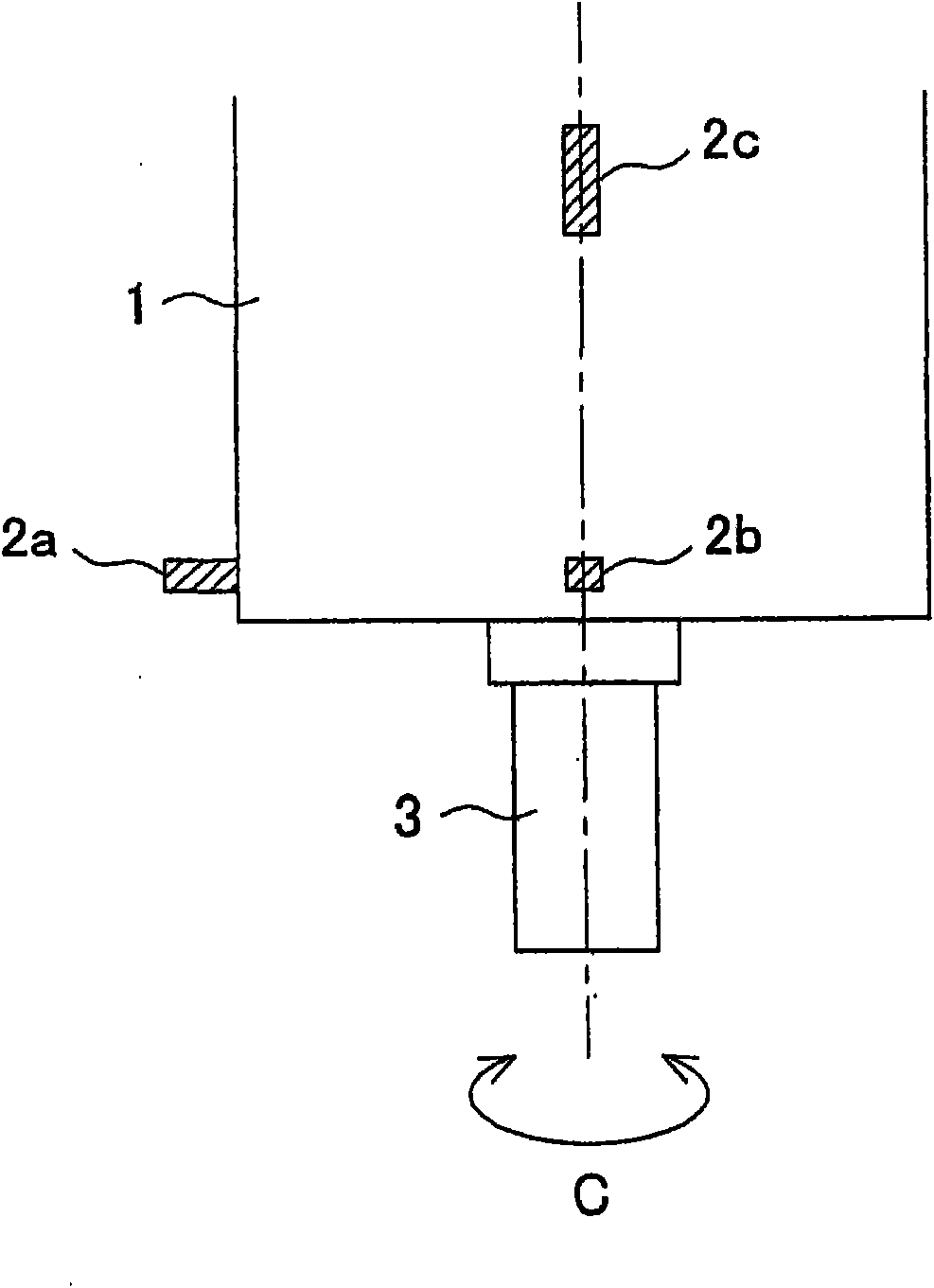
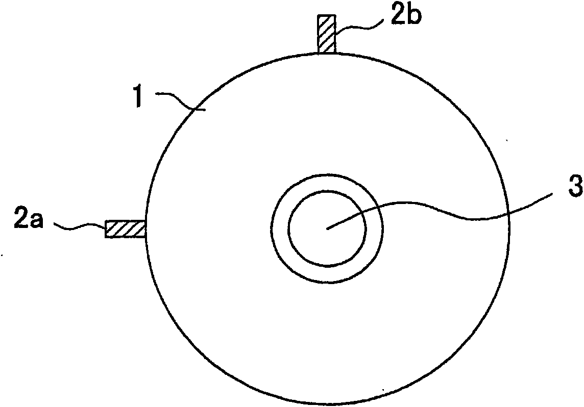
[0046] figure 1 It is a block diagram illustrating the configuration of the vibration suppression device 10 . figure 2 It is an explanatory diagram showing the rotary shaft box 1 as the object of vibration suppression from the side, image 3 It is an explanatory diagram showing the rotary shaft box 1 from the axial direction.

[0047] The vibration suppressing device 10 is used to suppress the "flutter" generated on the rotating shaft 3 arranged to rotate around the C-axis in the rotating shaft box 1. The vibration suppressing device 10 is composed of the following parts: vibration sensors (detection units) 2a- 2c, which is used to detect the vibration acceleration in the time domain (representing the vibration acceleration on the time axis) generated on the rotating rotating shaft 3; and the control device 5, which performs Control the rotational speed of the rotary axis 3.

[0048] like figure 2 and image 3 As shown, the vibration sensors 2a to 2c are installed on th...


PUM


Abstract

The present invention relates to a method and a device for suppressing vibration generated during machining in a machine tool for performing machining while rotating a tool or a work. A stable rotation speed is acquired by finely changing a rotation speed of a rotary shaft 3 based on an expected stable rotation speed, and calculating an amount of change of a k' number, and the like. Therefore, a more accurate rotation speed can be acquired, and 'chatter vibration' generated during machining can be suppressed more effectively than a conventional method. As a result, a quality of a workpiece surface can be improved, and a tool wear and the like can be suppressed.

Description

technical field [0001] The present invention relates to a method of suppressing vibration generated during machining in a machine tool that performs machining while rotating a tool or a workpiece, and to a vibration suppressing device capable of performing the method. Background technique [0002] Conventionally, as a vibration suppression method of a machine tool, for example, the method described in Patent Document 1 is known. In this vibration suppression method, in order to suppress the regenerative chatter vibration that is self-excited vibration, the natural frequency of the system that generates chatter, such as the tool or the workpiece, is obtained, and the natural frequency is divided by 60 times the natural frequency by the number of tool blades and A value obtained by a predetermined integer is used as a stable rotational speed, wherein the self-excited vibration is a cause of deterioration of the finishing accuracy of the machined surface. And, by performing ma...

Claims


Application Information

Patent Timeline
Patent Type & Authority Applications(China)
IPC IPC(8): B23Q11/00B23Q17/12
Inventor 稻垣浩
Owner OKUMA CORP
Why Eureka
Try Eureka