Storage device and beam for loom

A technology of bearing device and carrier, which is applied in the direction of bearing assembly, bearing, loom, etc., and can solve problems such as loss of precision

Inactive Publication Date: 2010-01-13
GROZ BECKERT KG
View PDF3 Cites 2 Cited by
  • Summary
  • Abstract
  • Description
  • Claims
  • Application Information

AI Technical Summary

Problems solved by technology

However, this scheme comes with

Method used


Image

  • Storage device and beam for loom
  • Storage device and beam for loom
  • Storage device and beam for loom

Examples


Embodiment Construction

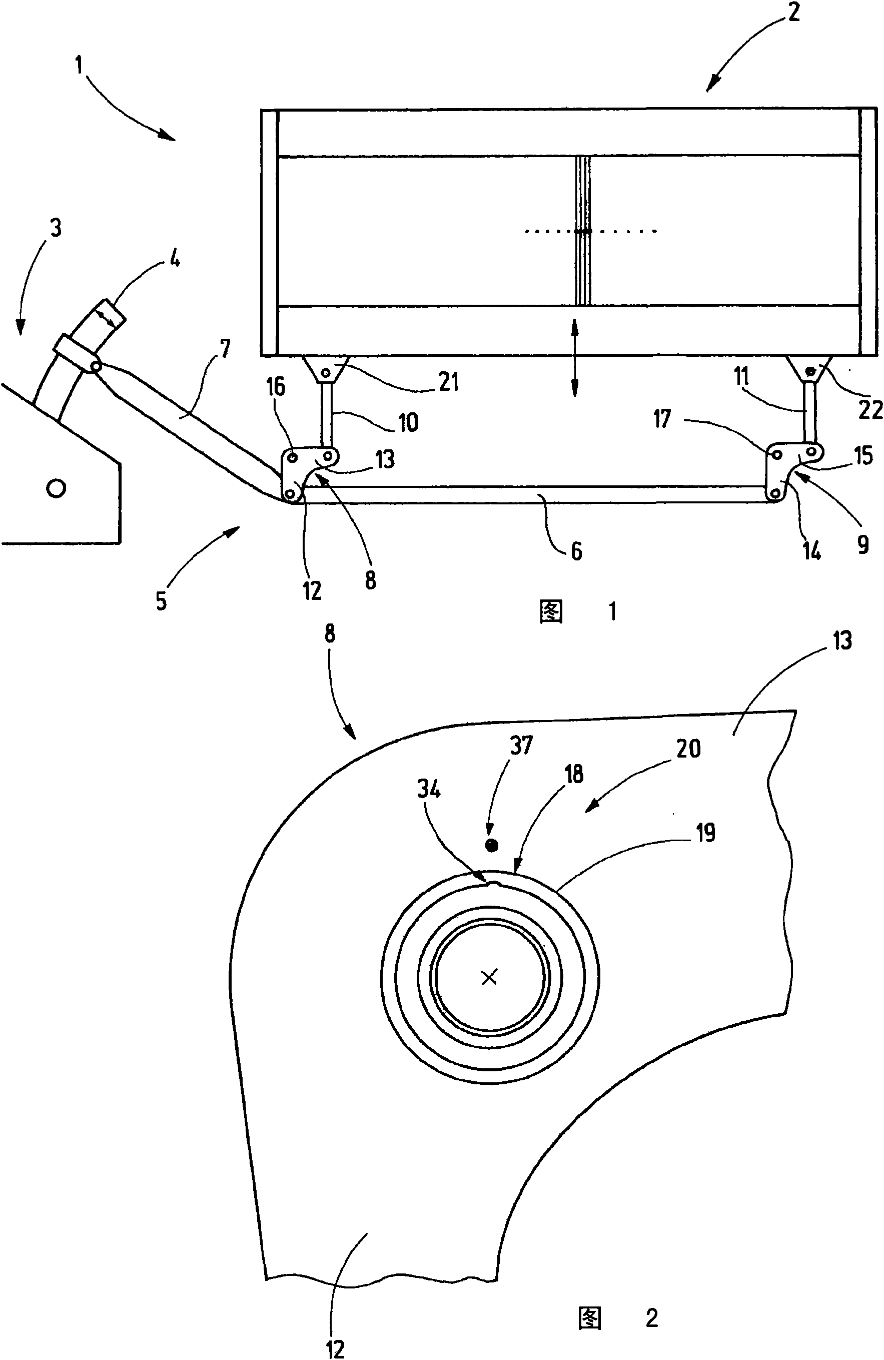
[0026] figure 1 A shedding machine 1 of a weaving machine is shown. Shedding machine 1 comprises heald frame 2, in figure 1 Only one of the heald frames is shown in . The heald frame 2 acts as a warp thread guide and moves up and down rapidly during operation, as figure 1 Indicated by double arrows. A drive machine 3 is used as the drive, the output of which is formed by a heald shaft 4 driven in an oscillating manner. Each heald frame 2 is associated with a heald frame rod 4 . The drive connection between the heald frame rod 4 and the heald frame 2 is formed by a carrier 5 representing a linkage. The carrier 5 comprises a transmission element in the form of at least one push-pull rod, also called load-bearing rod 6, at least one handle 7, at least two deflection rods 8, 9 and lifting rods 10, 11, said The shank 7 transmits the driving movement of the heald frame rod 4 to the rest of the rod assembly.

[0027] The deflection lever 8 is designed as a toggle lever. Each ...


PUM


Abstract

According to the invention, the antifriction bearing (18) needs not to open the outside lane (23). However, the outside lane (23) has a filling groove (34) for keeping unblock when being used. However, the diameter of the filling groove (34) is smaller than the diameter (D) of the ball, thereby the ball (25) does not fall off. In addition, the outside lane (23) of the bearing (18) displays a definite radial elastic. And the antifriction bearing (18) is radially and constrainedly installed through a pressing cooperation, thereby the ball (25) no longer jump out of the bearing (18). In order to assembly antifriction bearing (18) in an accurate angle, the filling groove (34) is out of the range of maximum stress. For this purpose, the filling groove (34) is preferably structured to cause the sealed ring (33) to keep existed and visible.

Description

technical field [0001] The invention relates to a bearing arrangement for a carrier of a loom and to such a carrier. Background technique [0002] A loom comprises a heald frame which carries the healds for guiding the warp threads. In operation, the heald frames perform rapid vertical movements. In order to impart this movement to the heald frame, a rod assembly is provided, which is also called a carrier. By means of such a carrier, each heald frame is connected to a driving machine. [0003] The carrier comprises, for example, push-pull rods extending horizontally below the heald frame. The carrier consists of a drive rod, optionally having a joint at each end, and a toggle rod, pivotally mounted to the frame. [0004] Due to the up and down movement of the heald frame, oscillation occurs at the support point. Such stresses require special bearing arrangements. The direction of rotation changes with the frequency of the loom. The radial force to be transmitted is o...

Claims


Application Information

Patent Timeline
IPC IPC(8): D03D51/02F16C35/06F16C19/06F16C33/58
CPCF16C43/08D03C1/144D03C1/14F16C41/008F16C35/067F16C33/58F16C19/06F16C43/06F16C2240/84F16C2340/00
Inventor J·布鲁斯克
Owner GROZ BECKERT KG
Why Eureka
Try Eureka