Adjustable multi-streaming type steam jet heat pump

A steam and heat pump technology, applied in the direction of jet pumps, pumps, non-volume pumps, etc., can solve the problems of large energy level difference, low heat pump efficiency, mechanical energy loss, etc., to reduce mechanical energy loss, improve heat pump efficiency, and reduce impact loss effect

Inactive Publication Date: 2010-01-13
HEBEI UNIVERSITY OF SCIENCE AND TECHNOLOGY
View PDF2 Cites 22 Cited by
  • Summary
  • Abstract
  • Description
  • Claims
  • Application Information

AI Technical Summary

Problems solved by technology

In the previous technology, due to the direct contact between high-grade steam and low-grade steam in the mixing chamber, the energy levels of the two are very different. The direct co

Method used


Image

  • Adjustable multi-streaming type steam jet heat pump

Examples


example 1

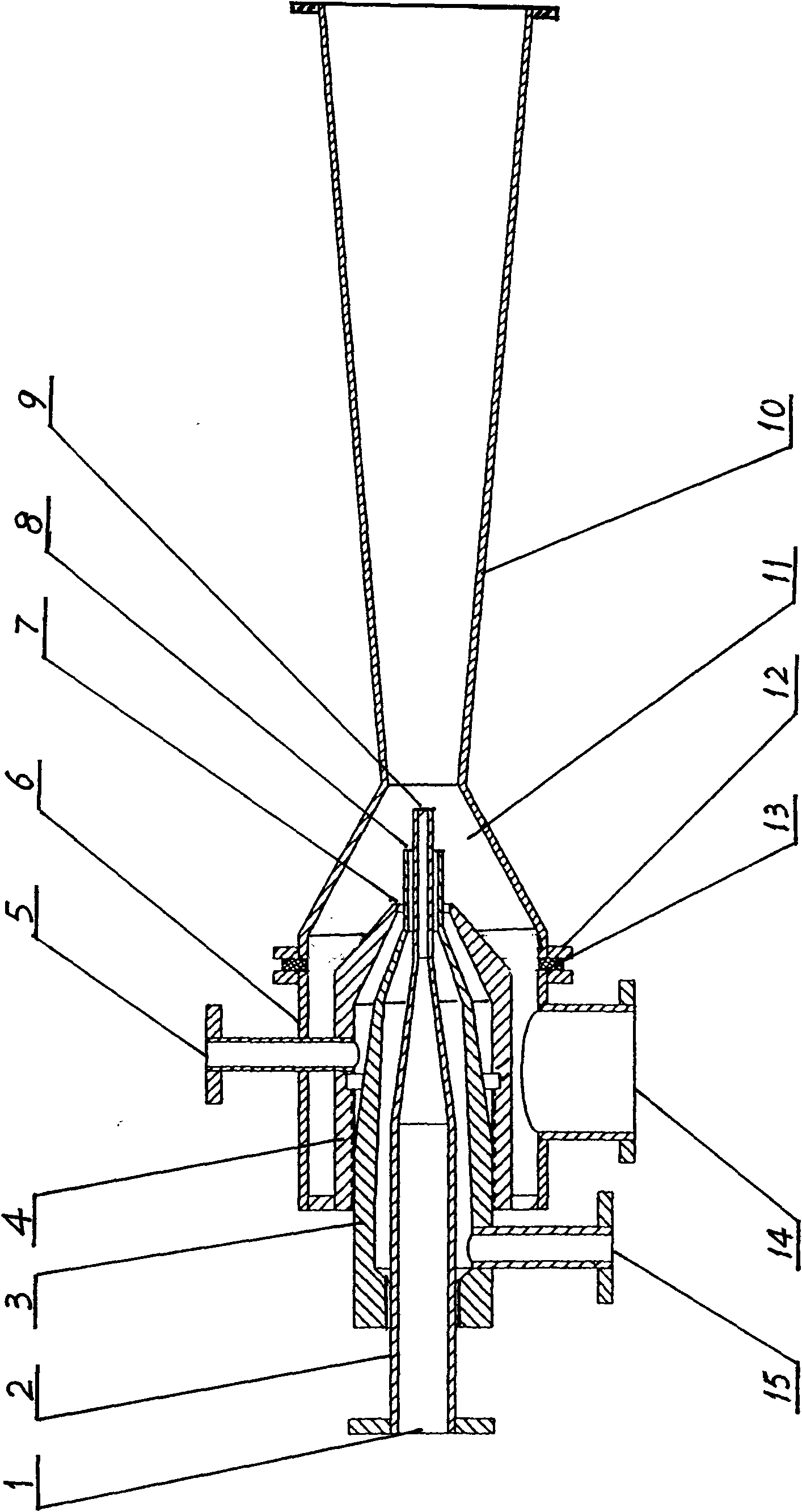
[0018] Such as figure 1 As shown, an adjustable multi-flow steam jet heat pump includes a pump body 6 in the structure. The pump body 6 is composed of a barrel-shaped shell and a cone-shaped pump port. The barrel-shaped shell and the cone-shaped pump port pass through The flange 12 is connected with a gasket 13 in the middle. By changing the thickness of the gasket 13, the distance between the outlet of the mixing chamber and the nozzle opening can be adjusted. The outer end of the cone-shaped central nozzle 2 located in the center of the pump body is provided with a working steam inlet 1. On the outer side of the cone-shaped central nozzle 2, one or more cone-shaped surrounding nozzles 3 with closed bottom ends are coaxially sleeved and fixed. 4. Commonly used are 2 to 3, the central nozzle and the surrounding nozzles and the surrounding nozzles are screwed together for easy installation and adjustment. A steam cavity is formed between the inner and outer cylinder walls of th...

Embodiment 2

[0020] This embodiment is an example of the use of an adjustable multi-flow steam jet heat pump. In the process of evaporation and concentration of a thermally sensitive material aqueous solution, the process requires that the evaporation temperature must be lower than 95°C. Double-effect evaporator is used. The first effect vacuum degree is 0.04MPa, the material temperature is 92°C, and the second steam temperature is 88°C; the second effect The vacuum degree is 0.095MPa, the material temperature is 80°C, and the secondary steam temperature is 70°C. The first effect uses 0.35MPa steam heating, and the second steam is pressurized by the steam jet heat pump as the second effect evaporator heating source. Using the adjustable three-flow steam jet heat pump described in Example 1 of the utility model, the working steam pressure of the central nozzle is 0.35MPa, the working steam pressure of the first annular nozzle is 0.25MPa, and the working steam pressure of the second annular n...


PUM


Abstract

The invention discloses an adjustable multi-streaming type steam jet heat pump. One or more than one conical-cylindrical surrounding nozzle with annular nozzle mouths are coaxially sleeved at the outer side of a conical-cylindrical central nozzle positioned in the center of a pump body, a nozzle mouth of the central nozzle is positioned at the topmost end and is in stepped arrangement with the annular nozzle mouths of the surrounding nozzles, the surrounding nozzles are respectively provided with a working steam inlet, a jet steam inlet is arranged on the lateral wall of the pump body, a cavity body at the front part of the pump body and the outer side of the nozzle mouth is of a steam mixed chamber, and the outer end of the steam mixed chamber is connected with the small mouth end of a diffusion tube. Working steam is jetted from the central nozzle in high speed, other strands of working steams are jetted from the nozzle mouths of the surrounding nozzles, a plurality of strands of steams form a certain-speed distribution field and act together so as to ensure that the pressure intensity at the nozzle mouths is reduced, and the jet steam is sucked in, and the steams are mixed through the steam mixed chamber, and slowed down and pressurized by the diffusion tube to generate jet stream with adjustable speed gradient, thereby the flow impact loss at the front edges of the nozzle mouths is effectively reduced, the energy loss is decreased, and the mechanical efficiency is improved.

Description

Technical field [0001] The invention relates to a steam jet heat pump, in particular to an adjustable multi-flow steam jet heat pump for improving steam grade, and belongs to the technical field of chemical equipment. Background technique [0002] In industrial production, especially in the field of chemical production, steam jet heat pumps are commonly used equipment. Its working principle is to use high-grade steam heat sources as working steam and low-grade steam heat sources as pilot steam. The working steam accelerates to form high-speed jets in the nozzles. Generate partial low pressure and inhale the ejected steam. After mixing, decelerate and pressurize, the ejector discharges the back pressure steam heat source between the high-grade steam heat source and the low-grade steam heat source to realize the secondary utilization of the low-grade steam heat source , To achieve the purpose of energy saving. Steam jet heat pumps are widely used in industrial processes due to the...

Claims


Application Information

Patent Timeline
IPC IPC(8): F04F5/16
Inventor 郑学明尚会建
Owner HEBEI UNIVERSITY OF SCIENCE AND TECHNOLOGY
Why Eureka
Try Eureka