Method for detecting coupling response of cable under excitation of electromagnetic wave

A detection method, electromagnetic wave technology, applied in the direction of measuring electricity, measuring devices, measuring electrical variables, etc.

Active Publication Date: 2010-01-13
BEIHANG UNIV
View PDF0 Cites 18 Cited by
  • Summary
  • Abstract
  • Description
  • Claims
  • Application Information

AI Technical Summary

Problems solved by technology

The common defect of these three models is that the model is described by the incident wave component, which requires prior knowledge of the incident wave information, and is n

Method used


Image

  • Method for detecting coupling response of cable under excitation of electromagnetic wave
  • Method for detecting coupling response of cable under excitation of electromagnetic wave
  • Method for detecting coupling response of cable under excitation of electromagnetic wave

Examples


Embodiment 1

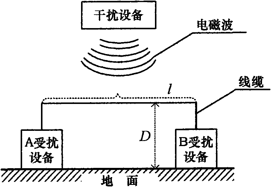
[0058] see Figure 5 As shown, the cable is connected between the disturbed device A and the disturbed device B, and the cable is subjected to the electromagnetic interference of the disturbing device A and the disturbing device B, and the cable coupling response detection is as follows:

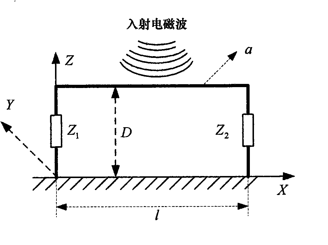
[0059] Cable parameters: l=1m, d=0.01m, a=0.0015m, Z 1 = Z 2 = 300Ω.

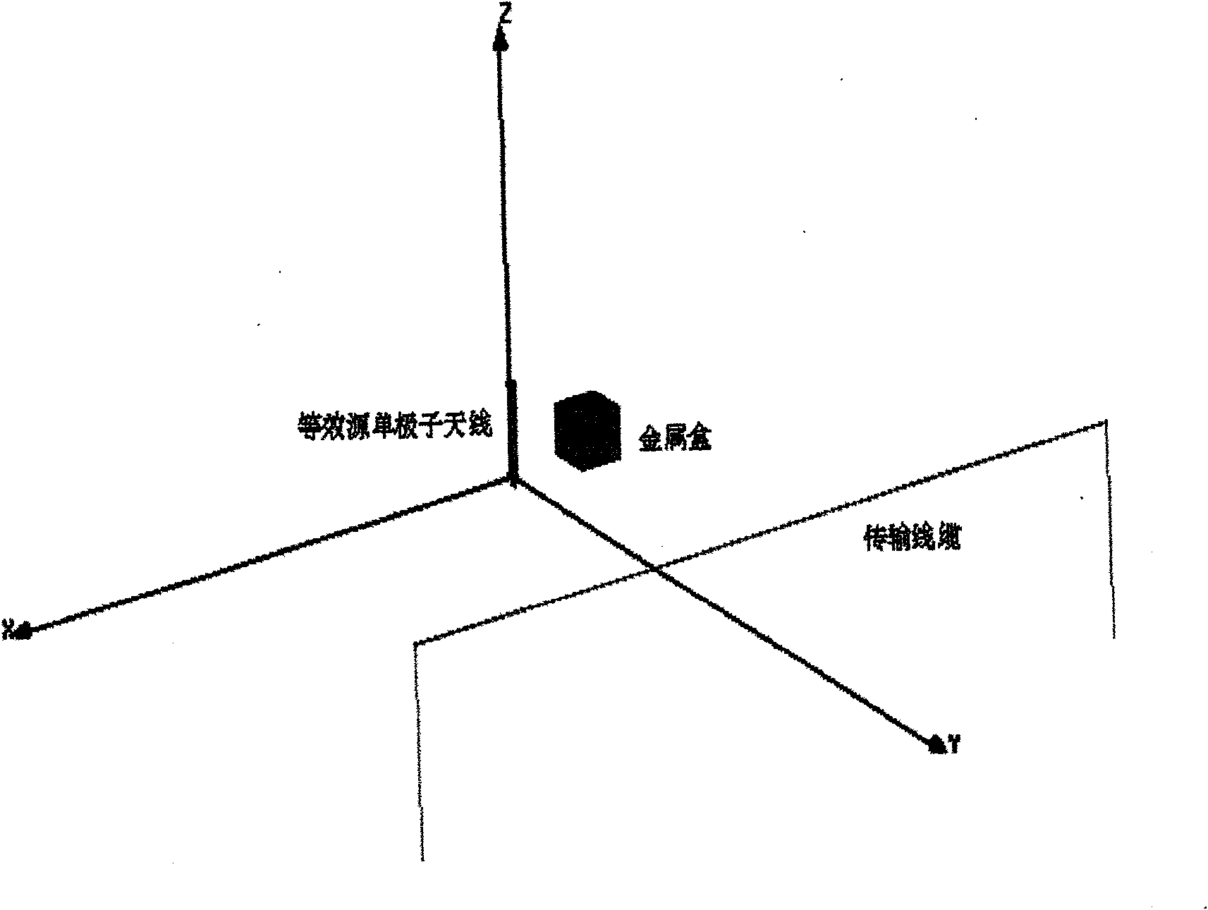
[0060] The A jamming device is equivalent to the first cylindrical monopole antenna (see Figure 2A shown), its length LA 1 =1.077×10 -4 m, radius LR 1 =5×10 -6 m, excitation source voltage amplitude v 1 =3V, phase φ 1 =25°, simulation frequency f=696.5MHZ.

[0061] Equivalent the B jamming device to a second cylindrical monopole antenna (see Figure 2A shown), its length LA 2 =8.965×10 -5 m, radius LR 2 =5×10 -6 m, excitation source voltage amplitude v 2 = 3.4V, phase φ 2 =-1.6°, simulation frequency f=836.5MHZ.

[0062] Cable boundary: Conductivity σ=5.7×10 7 (unit S / m), dielectric constant ε=8.85×10 ...

Embodiment 2

[0067] see Figure 5 As shown, the cable is connected between the disturbed device A and the disturbed device B, and the cable is subjected to the electromagnetic interference of the disturbing device A and the disturbing device B, and the cable coupling response detection is as follows:

[0068] Cable parameters: l=1m, d=0.01m, a=0.0015m, Z 1 = Z 2 = 300Ω.

[0069] The A jamming device is equivalent to the first rectangular monopole antenna (see Figure 2B shown), its length LA 1 =5×10 -6 m, width LB 1 =5×10 -6 m, high LC i =1.077×10 -4 m, excitation source voltage amplitude v 1 =3V, phase φ 1 =25°, simulation frequency f=696.5MHZ.

[0070] Equivalent the B jamming device to a second rectangular cylindrical monopole antenna (see Figure 2B shown), its length LA 2 =5×10 -6 m, width LB i =5×10 -6 m, high LC i =8.965×10 -5 m, excitation source voltage amplitude v 2 = 3.4V, phase φ 2 =-1.6°, simulation frequency f=836.5MHZ.

[0071] Cable boundary: Conductivi...


PUM

PropertyMeasurementUnit
Dielectric constantaaaaaaaaaa

Abstract

The invention discloses a method for detecting coupling response of a cable under the excitation of electromagnetic wave, which comprises the following steps: introducing an equivalent radiation source Si (Gi, Li,), the excitation Gi(gi, phi i) of the equivalent radiation source and cable border KL(1, a, D, sigma, epsilon, mu) into a numerical analysis platform of an electromagnetic field; and analyzing the introduced sources to obtain the current electromagnetic wave total field information Ei(ei, theta i). The invention combines an HFSS platform with a correction Taylor model (see the formula enclosed in the right drawing) under the radiation of a single interference source so as to obtain the terminal response of a cable used for connecting with two interfered devices under the radiation of electromagnetic waves generated by a plurality of interference devices. The method can be used for predicting the coupling response state of a cable under the excitation of incident electromagnetic wave so as to provide reference information for device level and system level electromagnetic compatibility designs.

Description

technical field [0001] The invention relates to a coupling response detection method, more particularly, a cable coupling response detection method applicable to electromagnetic wave excitation, and belongs to the field of electromagnetic compatibility technology coupling interference prediction. Background technique [0002] In electrical or electronic equipment, cables (cables or wires) are used to realize the connection between equipment and equipment, equipment and devices. When multiple devices work together, some devices will generate electromagnetic interference, which will be coupled to another device through cables, causing the performance of the other device to degrade or even fail to work normally. With the wide application of digital devices and integrated circuits, electronic devices are particularly sensitive to space electromagnetic fields, and the electromagnetic interference generated by space electromagnetic fields through the electromagnetic coupling of ca...

Claims


Application Information

Patent Timeline
IPC IPC(8): G01R31/00
Inventor 戴飞汪玉梅吴龙刚陈文青苏东林
Owner BEIHANG UNIV
Why Eureka
Try Eureka