Cut-off device for separating or connecting two parts of an electric circuit, including a voltage transformer

A technology for connecting circuits and circuit breakers, which is applied to circuits, inductors, transformers, etc., and can solve the problems of complex, clumsy, and expensive drive mechanisms

Inactive Publication Date: 2010-01-13
ALSTOM TECH LTD
View PDF7 Cites 3 Cited by
  • Summary
  • Abstract
  • Description
  • Claims
  • Application Information

AI Technical Summary

Problems solved by technology

The connecting rod is moved by means of a drive mechanism, which is complex and expensive
The circuit bre

Method used


Image

  • Cut-off device for separating or connecting two parts of an electric circuit, including a voltage transformer
  • Cut-off device for separating or connecting two parts of an electric circuit, including a voltage transformer
  • Cut-off device for separating or connecting two parts of an electric circuit, including a voltage transformer

Examples


Embodiment Construction

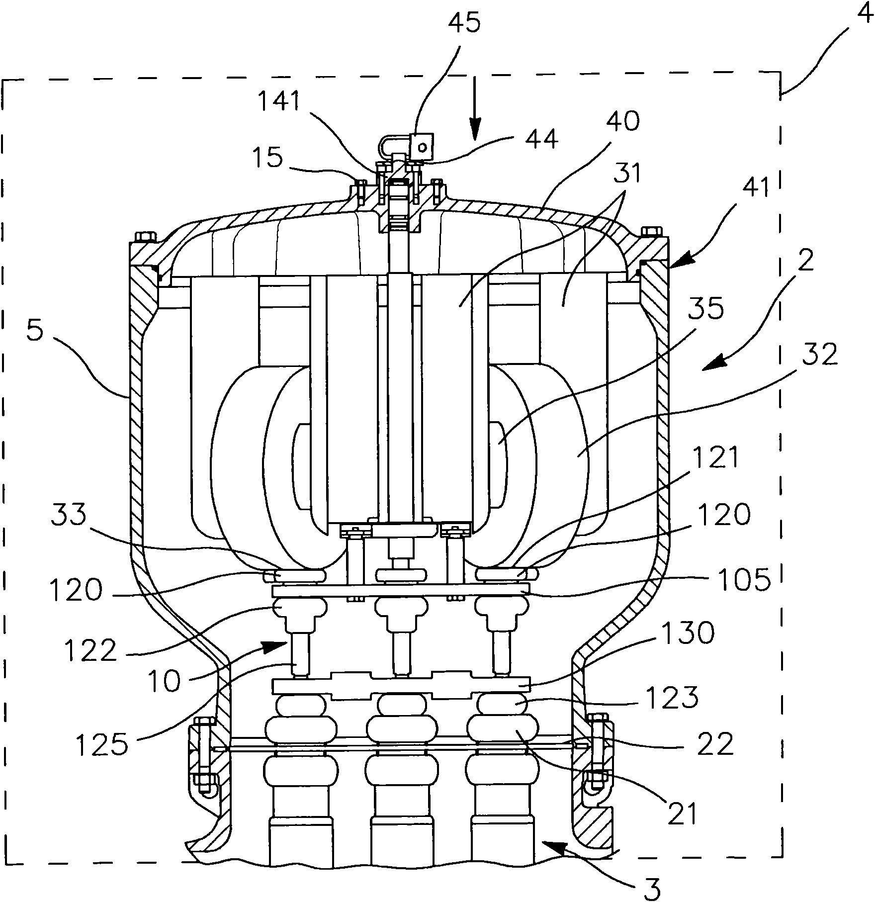
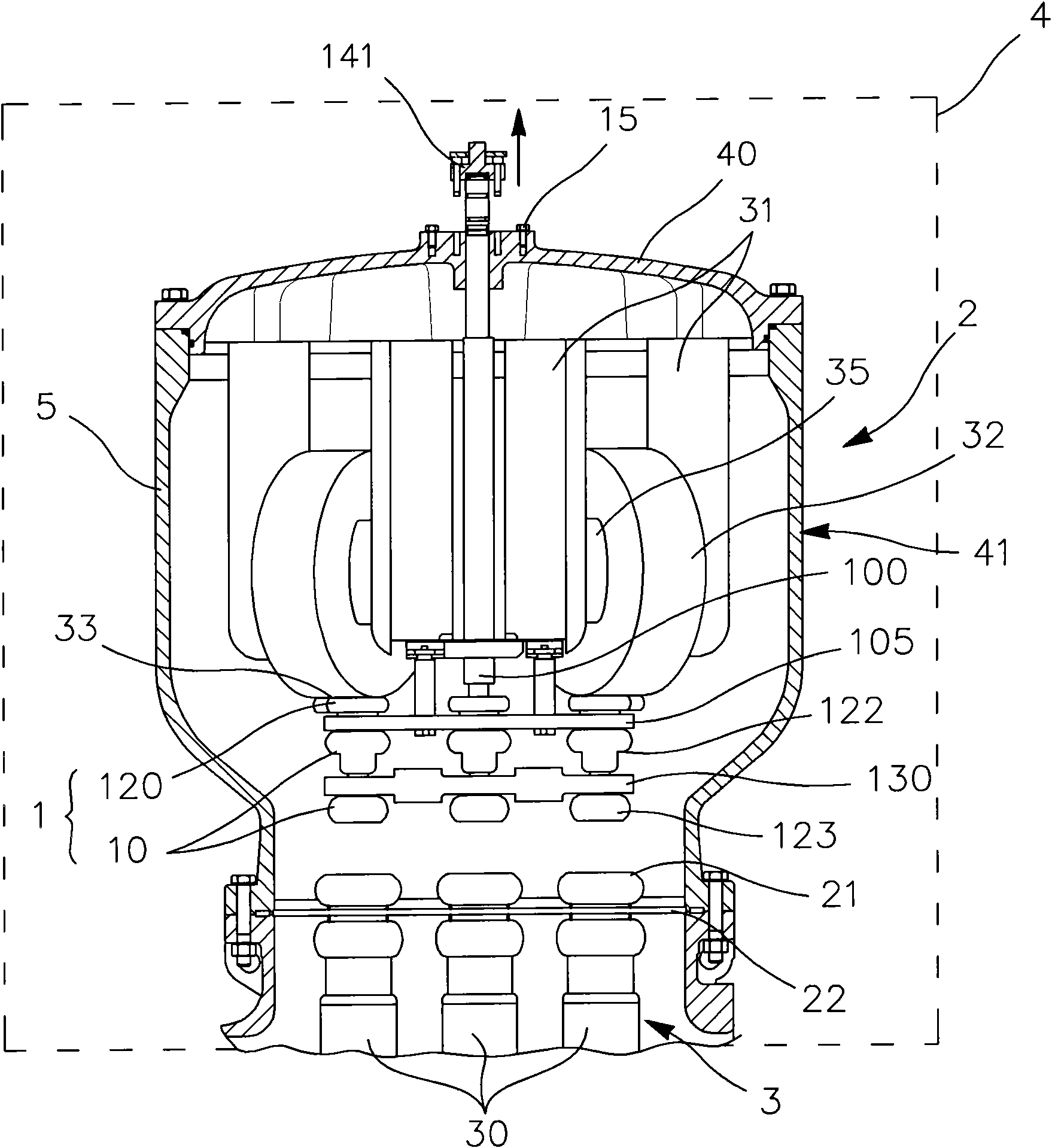
[0046] Referring now to the diagram illustrating a circuit breaker arrangement according to the present invention Figure 1A and 1B , said circuit breaker device is installed between two parts 2 and 3 of a high or medium voltage circuit 4 , one of which is a voltage converter 2 . Circuit 4 is a high or medium voltage gas insulated substation or armored substation. The substation 4 is shown diagrammatically in dashed lines.

[0047] The voltage converter 2 is located in the sealed chamber 41 . The sealed chamber 41 is usually filled with insulating gas, such as sulfur hexafluoride (SF 6 ). The sealed chamber is delimited by side walls 5 , base 22 and cover plate 40 . The base 22 of the chamber 41 is made of a dielectric material such as epoxy resin or eg thermoplastic polyester. Wall 5 and cover plate 40 are electrically conductive.

[0048] The other part 3 of the circuit is shown diagrammatically with one or more high or medium voltage conductors of a substation 4 .

...


PUM


Abstract

The device for cutting is used to separate or connect two portions (2, 3) of an electrical circuit, which comprises a transformer with a winding (32), and the device for cutting is adapted to take an open position or a closed position. The device comprises at least a pair of electrical contacts (123, 121) with a movable contact (123) and a fixed contact (121), the transformer via an element of connection (33) is contacted with the fixed contact by an elastic installation; a telescopic guiding device (10) having a fixed portion (122) and a sliding movable portion (125), and the fixed portion (122) is fixed relative to the fixed contact (121), and the movable portion supports the movable contact (123); a control device (100) for maintaining the telescopic guiding device (10) in extension when the cutting device is in a closed position, or the for maintaining the telescopic guiding device in retraction when the cutting device is in an open position. The pair of electrical contacts (121, 123), the telescopic guiding device (10) and the control device form an independent sub-component, for being assembled onto the transformer mechanically by means of the fixed device (6).

Description

technical field [0001] The invention relates to a circuit breaker device for separating or connecting two parts of an electric circuit comprising a voltage converter. [0002] Most particularly, the invention applies to the case where the circuit is part of a gas insulated substation (GIS) or an armored substation, in which it operates at medium or high voltage. The voltage transformers are located in the sealed chamber and form part of the substation. [0003] When the circuit breaker device is open, the voltage converter is electrically isolated from the rest of the substation and the substation can be operated without damage to the converter. [0004] A substation is a piece of equipment located at the junction of power transmission equipment and distribution lines, containing, inter alia, switching gear for protection, transformation and disconnection, designed to alter certain characteristics of the network to which it is connected according to operational requirements ...

Claims


Application Information

Patent Timeline
IPC IPC(8): H01H31/32H01H3/32H01H3/06H02B7/01
CPCH01F38/28H01H1/5844H01H1/5822H01F38/26H02B13/0356
Inventor C·吉梅诺H·希尔特布龙纳
Owner ALSTOM TECH LTD
Why Eureka
Try Eureka