
Permanent-magnet switch flux-linkage generator of three-dimensional magnetic structure

A technology of switching flux linkage and generator, applied in the shape/style/structure of magnetic circuit, synchronous motor with static armature and rotating magnet, rotating parts of magnetic circuit, etc., can solve the problem of complex winding structure and low power density , excessive magnetic flux leakage, etc., to achieve the effect of high winding utilization, conducive to manufacturing and insulation, and performance improvement

Inactive Publication Date: 2011-09-07
HARBIN INST OF TECH
View PDF0 Cites 2 Cited by
  • Summary
  • Abstract
  • Description
  • Claims
  • Application Information

AI Technical Summary

Problems solved by technology

[0009] The purpose of the present invention is to solve the problems of low power density, complex winding structure, and difficult-to-manufacture insulation of low-speed permanent magnet generators with the increase of power level, and the problem of excessive magnetic flux leakage when the number of poles of fractional slot permanent magnet motors is large, and provides Permanent magnet switch flux linkage generator with three-dimensional magnetic circuit structure

Method used


Image

  • Permanent-magnet switch flux-linkage generator of three-dimensional magnetic structure
  • Permanent-magnet switch flux-linkage generator of three-dimensional magnetic structure
  • Permanent-magnet switch flux-linkage generator of three-dimensional magnetic structure

Examples


specific Embodiment approach 1

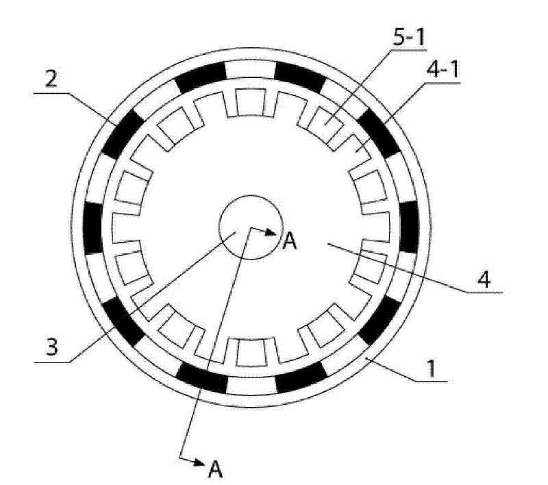
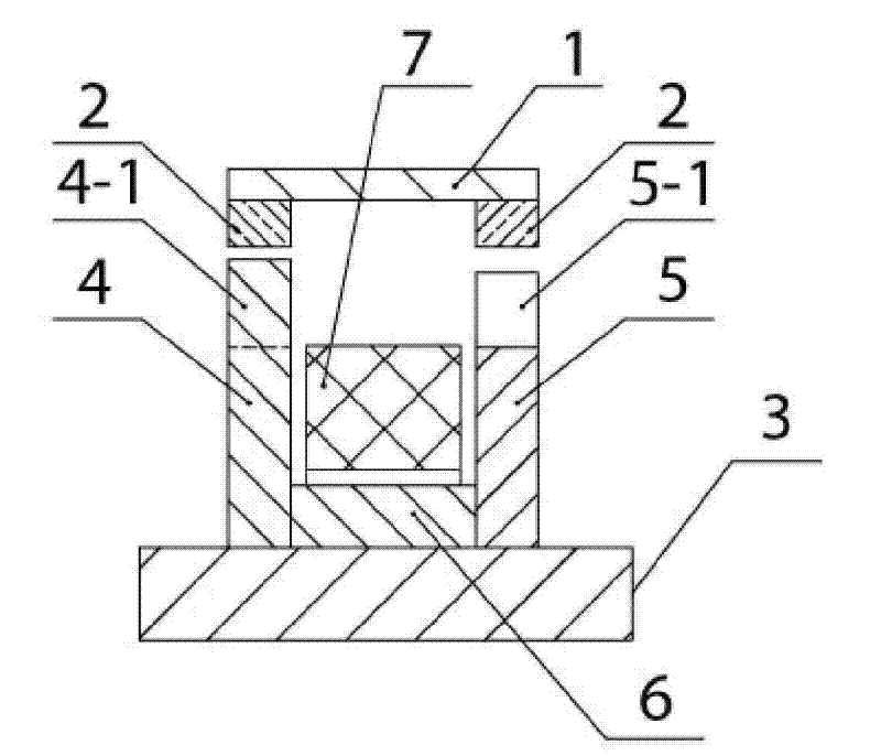
[0021] Specific implementation mode one: the following combination Figure 1 to Figure 4 Describe this embodiment, the single-phase permanent magnet switch flux linkage generator of the three-dimensional magnetic circuit structure described in this embodiment includes an outer rotor, a stator and a main shaft 3, the stator is located between the main shaft 3 and the outer rotor, and the stator and the main shaft 3 are fixed Fixed, characterized in that the outer rotor includes a rotor yoke 1, two rows of magnetic steel arrays 2, and the stator includes a first stator core 4, a second stator core 5, a magnetically conductive ring-shaped core 6 and a stator winding 7 ,

[0022] Along the axial direction of the main shaft 3, a first stator core 4, a magnetic connection ring core 6 and a second stator core 5 are arranged in sequence, the first stator core 4, a magnetic connection ring core 6 The inner surface of the second stator iron core 5 is fixedly connected with the outer su...

specific Embodiment approach 2

[0029] Embodiment 2: The difference between this embodiment and Embodiment 1 is that the stator winding 7 adopts a concentrated ring winding, and the others are the same as Embodiment 1.

[0030] There is only one axial concentrated winding for each phase, which is not only beneficial to manufacturing and insulation, but also has high utilization rate of the winding, greatly reduces the resistance and reactance of the winding, and greatly improves the performance of the generator. At the same time, there is no directly closed slot leakage magnetic circuit between the upper teeth or poles of the stator, which fundamentally solves the problem of excessive magnetic flux leakage when the fractional slot permanent magnet motor has a large number of poles.

specific Embodiment approach 3

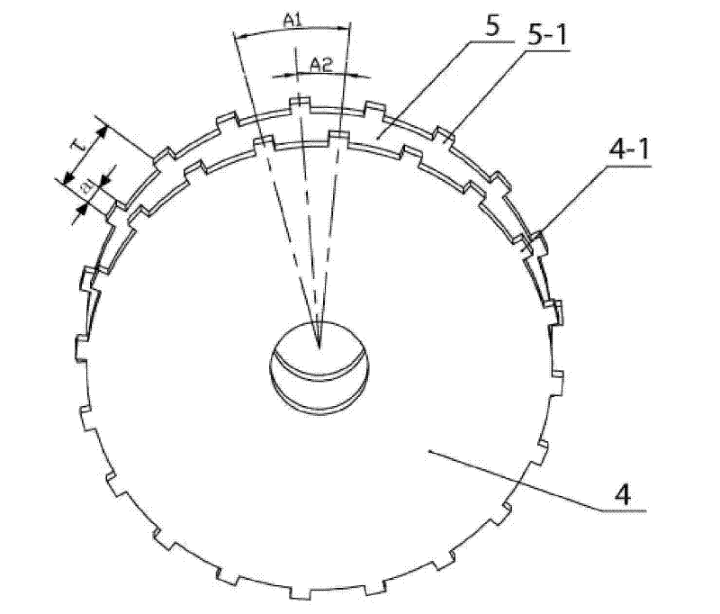
[0031] Embodiment 3: The difference between this embodiment and Embodiment 1 is that the salient pole width a of the first stator salient pole 4-1 is 0.3 to 0.4 times of the stator pole pitch τ, and the first stator salient pole 4 -1 is equal in size to the second stator salient pole 5-1, and the others are the same as those in the first embodiment.

[0032] The first stator core 4 and the second stator core 5 are exactly the same, and the first stator salient poles 4-1 and the second stator salient poles 5-1 uniformly distributed on the outer circular surfaces of the two iron cores are also the same, equal in size, It is only a uniform phase-staggered distribution, as shown in 3, the angle between the salient pole centerline of the second stator salient pole 5-1 and the salient pole centerline of the first stator salient pole 4-1 adjacent to the right is A2, and the phase The included angle between the centerlines of two adjacent first stator salient poles 4-1 salient poles i...


PUM


Abstract

The invention relates to a permanent-magnet switch flux-linkage generator of a three-dimensional magnetic structure, belonging to the field of electric motors and aiming to solve the problems of low power density, complex winding construction, difficult insulation manufacture, and the like which are existed in a low-speed permanent-magnet generator. A single phase generator of the invention has the technical scheme that two stator cores are arranged along the axial direction of the outer surface of a main shaft and are connected by a magnetic-inductive-connection toroidal core to form a toroidal groove in which a stator winding is arranged, salient poles on the two stator cores are mutually staggered a distance of half stator, an outer rotor consists of a rotor yoke and two rows of alnicoarrays arranged at the inner surface of the rotor yoke, one row of the alnico arrays is respectively arranged in the same level with one of the stator cores, and the axial center line of the two stator cores and the two rows of alnico arrays are overlapped. A two-phase generator of the invention consists of two single phase generators, rotor yoke connection pieces, supporting rings and main shaftconnection pieces, and the two single phase generators are of quadrature winding structures. On the basis of the two-phase generator, by distribution of number of windings and connection of the windings, a three-phase generator can be formed.

Description

technical field [0001] The invention relates to a permanent magnet switch flux linkage generator with a three-dimensional magnetic circuit structure, which belongs to the field of motors. Background technique [0002] Due to the advantages of high efficiency and high torque density, permanent magnet synchronous generators have certain advantages in many applications, including wind power generators and hybrid electric vehicle generators, and there is room for wide application. At present, common permanent magnet synchronous generator structures mainly include: radial magnetic field conventional motor structure with surface magnetic steel and built-in magnetic steel rotor structure, and axial magnetic field disc motor or axial magnetic field double stator structure motor. However, there are still many problems to be solved in the research and development of permanent magnet synchronous generators, including: [0003] (1) The power density of ordinary low-speed permanent magn...

Claims


Application Information

Patent Timeline
Patent Type & Authority Patents(China)
IPC IPC(8): H02K21/12H02K1/27H02K21/02
Inventor 孙立志孙力吴凤江赵克
Owner HARBIN INST OF TECH
Learn More