Refrigerating device
A refrigeration device and refrigerant technology, applied in refrigerators, refrigeration components, refrigeration and liquefaction, etc., to achieve the effect of ensuring reliability
- Summary
- Abstract
- Description
- Claims
- Application Information
AI Technical Summary
Problems solved by technology
Method used
Image

Examples
no. 1 approach
A first embodiment of the present invention will be described. This embodiment is an air conditioner 10 constituted by a refrigeration device according to the present invention.
[0042] (The overall structure of the air conditioner)
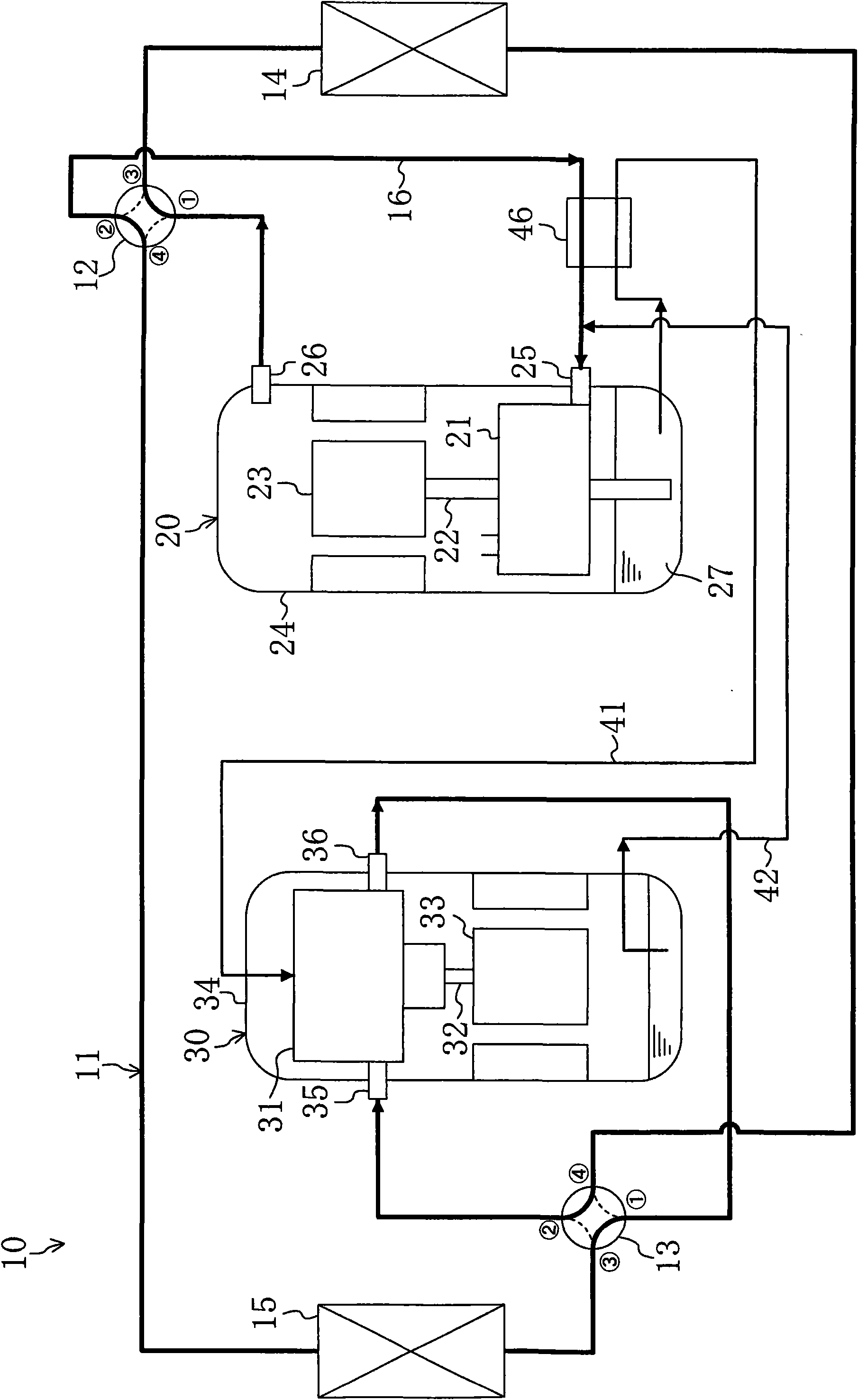
Such as figure 1 As shown, the air conditioner 10 in this embodiment includes a refrigerant circuit 11 . In the refrigerant circuit 11, the compressor 20, the expander 30, the outdoor heat exchanger 14, the indoor heat exchanger 15, the first four-way switching valve 12, and the second four-way switching valve 13 are connected together. The refrigerant circuit 11 is filled with carbon dioxide (CO 2 ) as refrigerant. Further, the refrigerant circuit 11 is provided with an oil supply pipe 41 , an oil return pipe 42 , and a cooling heat exchanger 46 .
[0043] The configuration of the refrigerant circuit 11 will be described. The discharge pipe 26 of the compressor 20 is connected to the first port of the first four-way reversing valve 12 ; the...
no. 2 approach
A second embodiment of the present invention will be described. In this embodiment, the expander casing 34 has the function of a liquid reservoir. Here, differences between the air conditioner 10 in this embodiment and the first embodiment described above will be described.
[0106] Such as Figure 7 As shown, in the refrigerant circuit 11 of the present embodiment, the suction-side piping 16 is composed of the first piping 17 and the second piping 18 .
[0107] One end of the first pipeline 17 is connected to the second port of the first four-way reversing valve 12, the other end of the first pipeline 17 is connected to the expander casing 34, and the port of the other end is located at the expander casing 34. Between the expansion mechanism 31 and the generator 33 in the inner space. The first pipe 17 constitutes a first suction-side passage that communicates the heat exchanger functioning as an evaporator among the indoor heat exchanger 15 and the outdoor heat exchanger 1...
no. 3 approach
A third embodiment of the present invention will be described. The air conditioner 10 in this embodiment is obtained by changing the structure of the expander 30 in the above-mentioned first embodiment. Here, differences between the expander 30 in this embodiment and the first embodiment described above will be described.
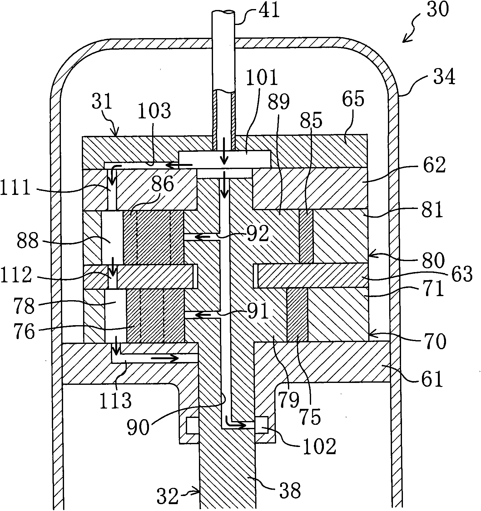
[0116] Such as Figure 9 As shown, an eccentric portion 59 is formed on the upper end portion of the output shaft 32 . The diameter of the eccentric portion 59 is formed larger than the diameter of the main shaft portion 38 of the output shaft 32 . An oil supply passage 90 is formed on the output shaft 32 . The oil supply passage 90 extends along the axis of the output shaft 32 . A port at one end of the oil supply passage 90 is located on the upper end surface of the output shaft 32 . The other end of the oil supply passage 90 is bent at right angles and extends radially of the output shaft 32 , and the opening of the other end is located on the outer ...
PUM
 Abstract
Description
Claims
Application Information
 - R&D
- Intellectual Property
- Life Sciences
- Materials
- Tech Scout
- Unparalleled Data Quality
- Higher Quality Content
- 60% Fewer Hallucinations
Browse by: Latest US Patents, China's latest patents, Technical Efficacy Thesaurus, Application Domain, Technology Topic, Popular Technical Reports.
© 2025 PatSnap. All rights reserved.Legal|Privacy policy|Modern Slavery Act Transparency Statement|Sitemap|About US| Contact US: help@patsnap.com