High-pressure water cleaning machine

A cleaning machine and high-pressure water technology, applied to cleaning methods and appliances, cleaning methods using liquids, chemical instruments and methods, etc., can solve the problems of low life, high noise, and low efficiency of high-pressure water cleaning machines, and achieve noise reduction , prolong the service life, and facilitate the effect of restarting

Inactive Publication Date: 2011-02-16
JIAHE TOOLS
View PDF0 Cites 0 Cited by
  • Summary
  • Abstract
  • Description
  • Claims
  • Application Information

AI Technical Summary

Problems solved by technology

[0004] The purpose of the present invention is to provide a high-pressure water cleaning machine, which can effectively solve the problem of low efficiency, high noise, and short lifespan of the existing high-pressure water cleaning machine that the rotary motor achieves reciprocating motion through the crankshaft connecting rod to drive the piston or the swash plate to rotate to make the plunger reciprocate. low problem

Method used


Image

  • High-pressure water cleaning machine
  • High-pressure water cleaning machine
  • High-pressure water cleaning machine

Examples


Embodiment 1

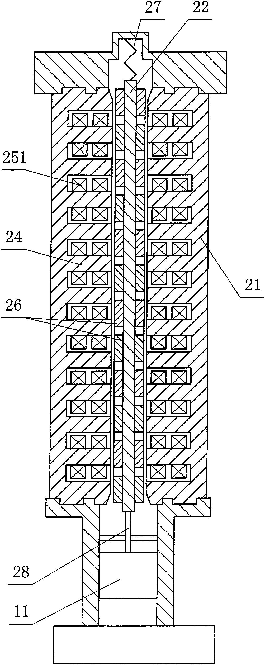
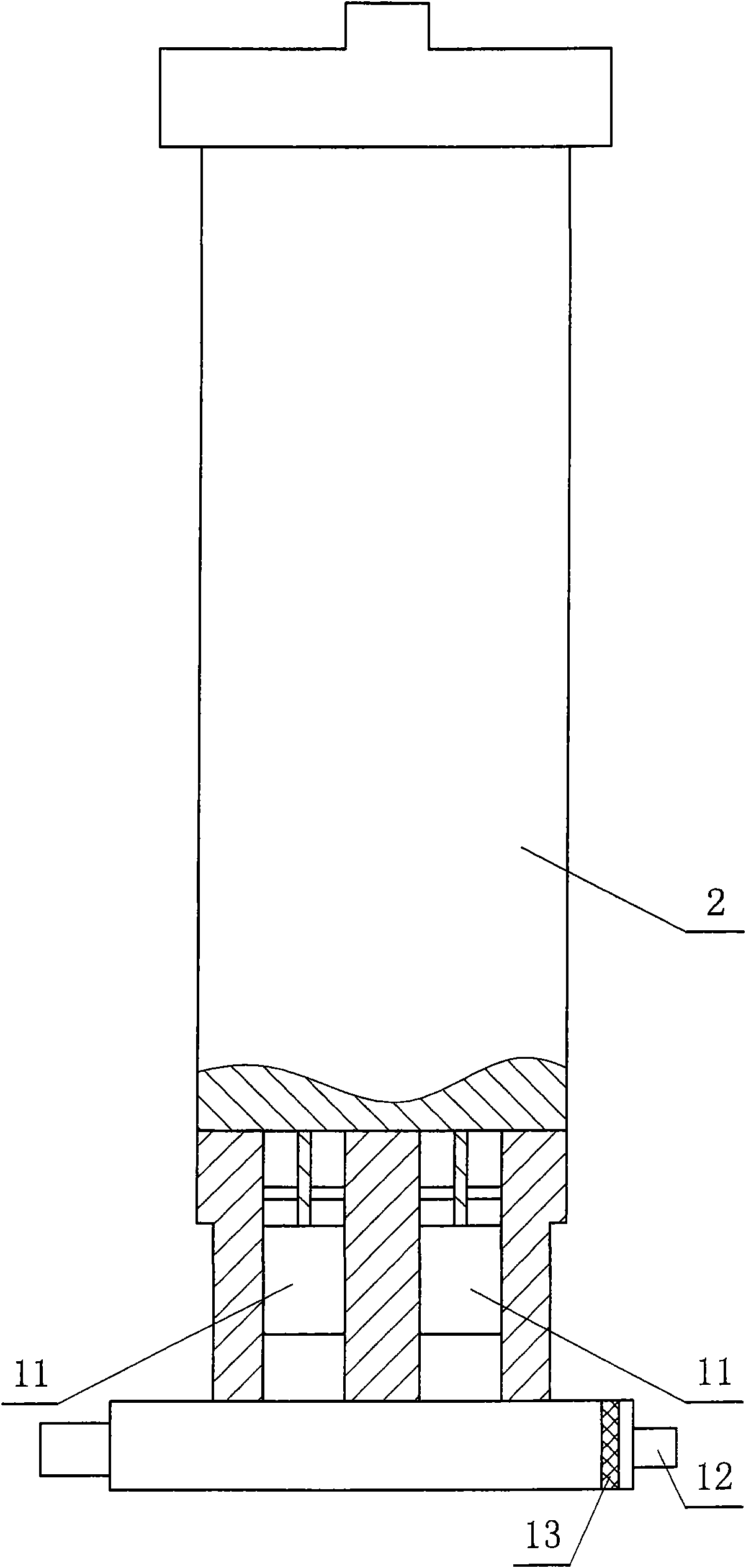
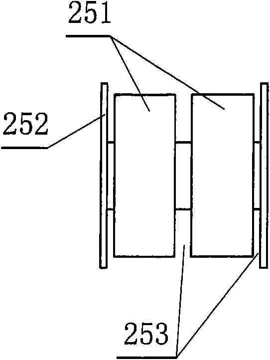
[0025] refer to figure 1 , figure 2 It is the first embodiment of a high-pressure water cleaning machine of the present invention, a high-pressure water cleaning machine, including a water pump 1, a piston 11 and a water body filter 13 arranged at the water inlet 12 are arranged in the water pump 1, and a motor 2. The motor 2 includes a stator 21 and a magnetic core yoke 22. A through hole 23 is provided in the center of the stator 21, and at least one set of stator cores 24 perpendicular to the axis of the through hole 23 are arranged on the wall of the through hole 23. The stator core 24 is provided with an electromagnetic coil 251, the magnetic core yoke 22 is provided with two or more pairs of magnetic steel 26, the magnetic steel 26 N poles and S poles are arranged alternately, and the magnetic core yoke 22 is arranged in the through hole 23, one end of the magnetic core yoke 22 is provided with two connecting rods 28 connected to the piston 11 of the water pump 1, and ...

Embodiment 2

[0027] refer to Figure 6 It is the second embodiment of a high-pressure water cleaning machine of the present invention, a high-pressure water cleaning machine, including two water pumps 1, the connection with one of the water pumps 1 and the internal and external structure of the motor 2 are the same as in the first embodiment. The other end of the yoke 22 is also provided with at least one connecting rod 28 to be connected with the piston 11 of the second water pump 1, the compression spring 27 is sleeved on the connecting rod 28, and one end of the compression spring 27 withstands the magnetic core yoke 22, and the compression spring 27 The other end bears against the casing of the water pump 1 .

[0028] When in use, connect the pipelines of the water inlet 12 and the water outlet, and energize the motor 2. After the electromagnetic coil 251 inside the motor 2 is energized, the magnetic poles generated continuously change and interact with the magnetic steel 26 on the mag...


PUM


Abstract

The invention relates to a high-pressure water cleaning machine comprising at least one water pump and a motor, wherein the water pump is internally provided with a piston and a water body filter arranged at the position of a water inlet; the motor comprises a stator and a magnetic core yoke, wherein the center of the stator is provided with a through hole, the wall of the through hole is provided with at least one group of stator iron cores perpendicular to a through hole shaft line, and the stator iron core is provided with an electromagnetic coil; the magnetic core yoke is provided with a magnet steel with more than two groups of poles, the N pole and the S pole of the magnet steel are staggered, the magnetic core yoke is arranged in the through hole, one end of the magnetic core yoke is provided with at least one connecting bar connected with the piston of the water pump, and the magnetic core yoke is also provided with an elastic resetting device. The invention improves the innerstructure of the motor so that the magnetic core yoke directly reciprocate to drive the piston in the motor, thereby effectively enhancing the work efficiency, reducing noise and prolonging the service life of the integral machine; in addition, the invention can appoint a resetting position by the elastic resetting device, thereby being convenient to start again.

Description

technical field [0001] The invention relates to a high-pressure water cleaning machine. Background technique [0002] The main principle of the high-pressure water cleaning machine is to generate high-pressure water by a high-pressure pump, and convert the high-pressure water into a high-speed water jet through the nozzle to strike, erode, and peel off the cleaning object to achieve the purpose of cleaning and descaling. It has the obvious advantages of high cleaning efficiency, good effect, no pollution, no corrosion of pipelines, low labor intensity of workers, saving raw materials, beneficial to environmental protection, and strong versatility. [0003] The current high-pressure water cleaning machine is mainly driven by the motor to reciprocate through the crankshaft connecting rod to drive the piston or the swash plate to reciprocate the plunger, but the general efficiency is low, the noise is large, and the service life is low. Contents of the invention [0004] The...

Claims


Application Information

Patent Timeline
Patent Type & Authority Patents(China)
IPC IPC(8): B08B3/02
Inventor 姜卫亮应时立
Owner JIAHE TOOLS
Why Eureka
Try Eureka