Novel moment limiter for crane

A torque limiter and crane technology, applied to cranes and other directions, can solve problems such as the inability to accurately grasp the position and real-time status of the crane, the failure of the torque limiter to work normally, and the error alarm of the torque limiter. It is suitable for promotion, complete functions, The effect of ensuring safe operation

Inactive Publication Date: 2010-01-20
宜昌市创星电子技术发展有限公司
View PDF0 Cites 5 Cited by
  • Summary
  • Abstract
  • Description
  • Claims
  • Application Information

AI Technical Summary

Problems solved by technology

[0002] Due to the needs of safe production, the current cranes are equipped with torque limiters with safety protection functions when they leave the factory. The existing torque limiters have the following disadvantages: First, due to the extremely harsh operating environment of truck cranes, the arm length of the torque limiter The sensor detection line is often hung up so that the torque limiter cannot work normally. The manufacturer must send professional technicians to deal with it on the spot or send it to the manufacturer for repair. As a result, the operation of the crane is in an unprotected state during this time, which seriously affects safe production; The hydraulic sensor is installed on the rod cavity and the rodless cavity of the luffing cylinder. Due to the complex internal pressure change of the hydraulic system, affected by the internal pressure of the system, the hydraulic sensor often drifts in zero position, and the error increases, resulting in torque limiter Generate false alarms and wrong actions, affecting safe production; third, there is no remote monitoring and maintenance function. If the crane is working outside, the monitoring personnel in different places cannot accurately grasp the crane’s position and real-time status. Loss of control without operator action

Method used


Image

  • Novel moment limiter for crane
  • Novel moment limiter for crane
  • Novel moment limiter for crane

Examples


Embodiment Construction

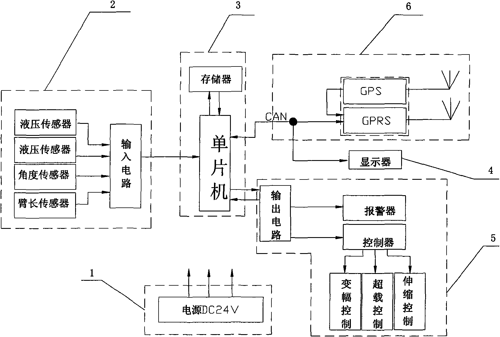
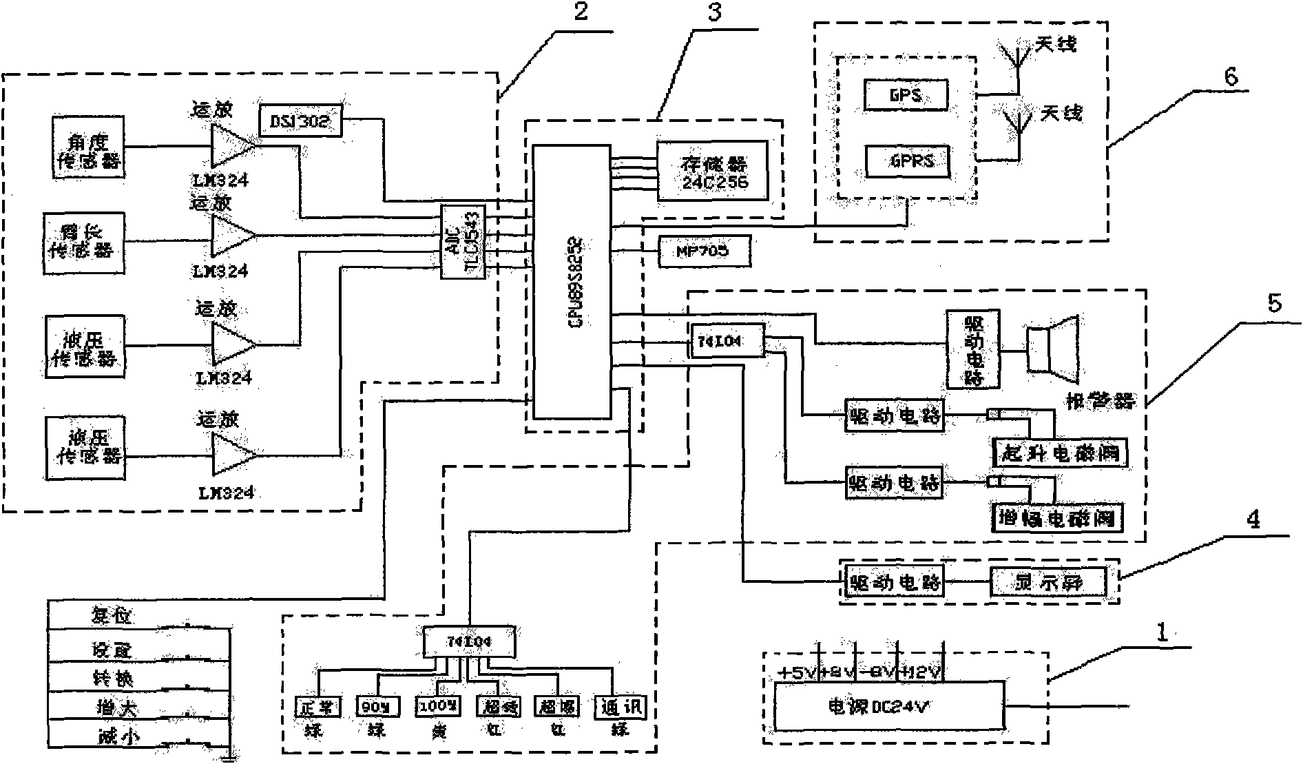
[0024] Such as figure 1 with figure 2 As shown, the present invention includes a power supply module 1, which also includes a data acquisition module 2, a data processing module 3, a data display module 4, a control module 5 and a remote monitoring and maintenance module 6, in which:

[0025] In the data acquisition module 2, the hydraulic sensors, angle sensors and boom length sensors respectively installed in the corresponding parts of the crane are connected to the input circuit. The hydraulic sensors and boom length sensors can be manually adjusted to realize zero self-tuning;

[0026] In the data processing module 3, the single-chip microcomputer is connected with the memory, the single-chip microcomputer is connected with the input circuit, and the data processing and control programs are stored in the memory;

[0027] In the control module 5, the controller is connected with the single-chip microcomputer through the output circuit, and the alarm is connected with the single-ch...


PUM


Abstract

The invention provides a novel moment limiter for cranes, comprising a power module, a data acquisition module, a data processing module, a data display module, a control module and a remote monitoring maintenance module; in the data acquisition module, a hydraulic sensor, an angle sensor and an arm length sensor, which are respectively arranged at corresponding positions of a crane, are connected with an input circuit, and the hydraulic sensor and the arm length sensor can be manually adjusted so as to achieve zero-position self-adjustment; in the data processing module, a single chip computer is connected with a memory and the input circuit; in the data display module, a display is connected with the single chip computer; in the control module, a controller is connected with the single chip computer through an output circuit, and an alarm is connected with the single chip computer through the output circuit; in the remote monitoring maintenance module, a GPS / GPRS module is connected with the single chip computer through a CAN communication circuit. The novel moment limiter for cranes ensures the accuracy and normal operation of a safety protection system, and has the advantages of simple structure, convenient operation and strong popularization.

Description

Technical field [0001] The invention relates to a safety protection device for cranes, in particular to a novel torque limiter for cranes. Background technique [0002] Due to the need of safe production, the current cranes are equipped with torque limiters with safety protection function when they leave the factory. The existing torque limiters have the following disadvantages: First, the use environment of truck cranes is extremely harsh and the arm length of the torque limiter The sensor detection line is often hung up so that the torque limiter cannot work normally. The manufacturer must send professional technicians for on-site treatment or send it to the manufacturer for repair, which causes the crane to operate in an unprotected state during this time, which seriously affects safe production; The hydraulic sensor is installed on the rod cavity and the rodless cavity of the luffing cylinder. Due to the complicated changes in the internal pressure of the hydraulic system and...

Claims


Application Information

Patent Timeline
Patent Type & Authority Applications(China)
IPC IPC(8): B66C23/88
Inventor 陈家忠王进潘兵
Owner 宜昌市创星电子技术发展有限公司
Why Eureka
Try Eureka