Worm wheel with rotating teeth

A technology of rotating gears and worm gears, applied to components with teeth, belts/chains/gears, portable lifting devices, etc., can solve problems such as difficult processing and complex transmission device structure, and achieve low processing and manufacturing costs. Precious metals, the effect of reducing manufacturing costs

Inactive Publication Date: 2010-01-20
李正心
View PDF1 Cites 5 Cited by
  • Summary
  • Abstract
  • Description
  • Claims
  • Application Information

AI Technical Summary

Problems solved by technology

In response to these problems, the application number is 021329357, which discloses a worm gear and worm ball thrust bearing transmission. In this patent, the worm gear is used as the bearing outer cover, and the worm is used as

Method used


Image

  • Worm wheel with rotating teeth
  • Worm wheel with rotating teeth

Examples


Embodiment 1

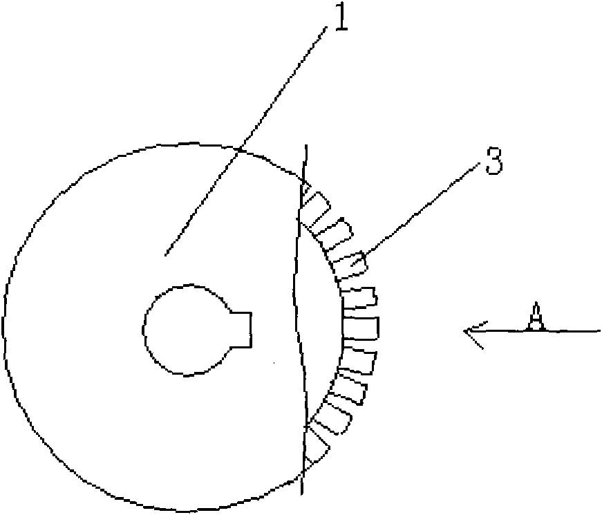
[0015] Such as figure 1 As shown, a worm wheel with rotating teeth includes a wheel body and worm teeth arranged on the outer edge of the wheel, and the worm teeth are matched with the worm.

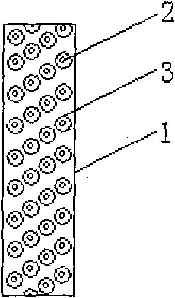
[0016] Such as figure 1 , 2 As shown, the worm gear is composed of a shaft 2 and a bearing 3 arranged on the tooth track. The shaft 2 is fixedly connected to the wheel body 1 and arranged in equal parts on the tooth track, and the outer diameter of the bearing 3 assembled on the shaft 2 is equal to the tooth track width.

[0017] In this embodiment, the worm wheel body 1, the shaft 2 arranged on the outer edge of the wheel body 1, and the outer casing of the bearing 3 assembled on the shaft 2 are made of steel material (high-quality carbon steel structure can be used).

Embodiment 2

[0019] A worm wheel with rotating teeth includes a wheel body and worm teeth arranged on the outer edge of the wheel, and the worm teeth are matched with the worm. The worm gear is composed of a bearing 3 and a shaft 2 arranged on the tooth track, and a blind hole (not shown in the figure) is arranged on the wheel body 1, and the bearing 3 is plugged into the blind hole and fixedly connected (the outer end of the bearing 3 is connected to the outer end of the wheel body) edge on one face), the shaft 2 assembled on the bearing 3 extends out of the diameter of the bearing 3 part and the equal width of the tooth track.

[0020] All the other implementations are as in Example 1.


PUM


Abstract

The invention discloses a worm wheel with rotating teeth, comprising a wheel body and worm teeth arranged on the outer edge of the wheel body. The worm teeth are matched with a worm. The worm wheel is characterized in that each worm tooth consists of a shaft arranged on a tooth path and a bearing or a shaft sleeve. The shaft is fixed to the wheel body and arranged uniformly on the tooth path, and the outside diameter of the bearing or the shaft sleeve jacketed on the shaft is as wide as the tooth path. The worm wheel has the shaft arranged on the outer edge of the worm wheel body only, is provided with the bearing or the shaft sleeve to form the tooth and also has the advantages of simple structure, low processing and manufacturing cost, small drive friction force and little power loss. Since the drive friction force of the worm wheel is small in the working process, the wheel body and a wheel tooth (including the shaft, the bearing or the shaft sleeve arranged on the shaft) can be made of general steel material, thereby reducing the manufacturing cost of the worm wheel.

Description

Technical field: [0001] The invention relates to the field of mechanical transmission, in particular to a worm wheel of a speed reducer. Background technique: [0002] At present, conventional worm and gear transmissions have the defects of large friction, low mechanical efficiency, and large power loss. In order to overcome these defects, in recent years, technicians in this field have continued to explore and research, and made good progress. A worm gear transmission that reduces friction and improves mechanism efficiency. For example, application number 85107587 discloses a steel ball circulating rolling worm reducer, which uses circulating rolling steel balls to transmit power between the worm and worm gear teeth; Composed of movable tooth worm, worm, ball, ball guide rail and ball circuit, it can realize variable speed transmission. The above-mentioned device still has some problems in actual operation, which need to be further solved. For example, when the worm is ru...

Claims


Application Information

Patent Timeline
IPC IPC(8): F16H55/22F16H55/17F16H55/06
Inventor 李正心
Owner 李正心
Why Eureka
Try Eureka