
Matching current mirror

A technology of matching current and current mirror, applied in the field of current mirror, can solve problems such as current replication error

Inactive Publication Date: 2010-01-20
曹先国
View PDF0 Cites 16 Cited by
  • Summary
  • Abstract
  • Description
  • Claims
  • Application Information

AI Technical Summary

Problems solved by technology

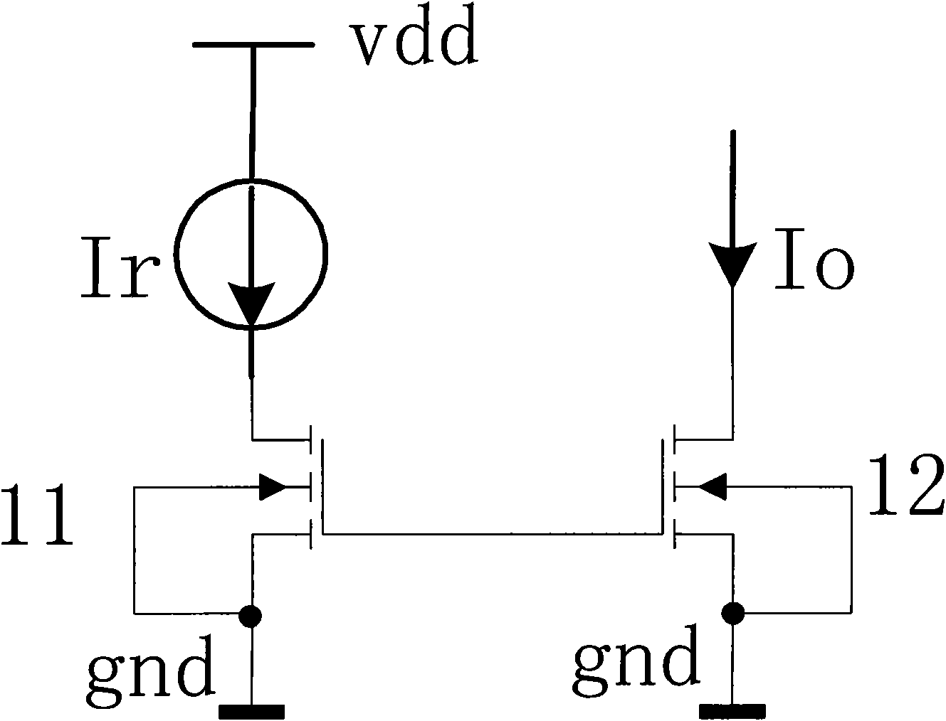
However, the ratio of Io and Ir is also affected by their respective drain-source voltages. The drain and gate voltages of the M1 tube are equal, but the drain voltage of the 12 tube may be biased at any voltage according to needs, which causes errors in current replication.

Method used


Image

  • Matching current mirror
  • Matching current mirror
  • Matching current mirror

Examples


Embodiment Construction

[0016] specific implementation

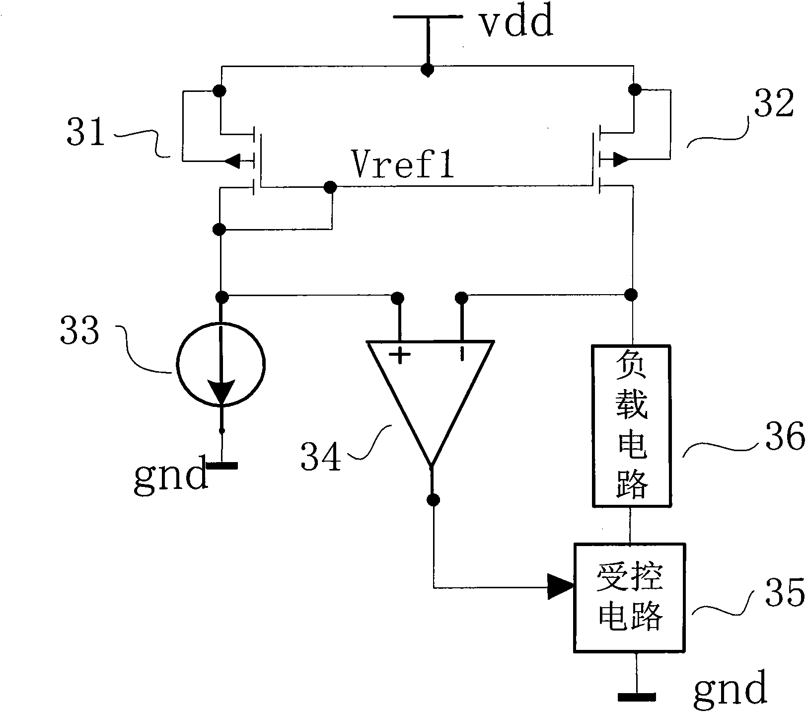
[0017] Embodiments of the present invention will be described with reference to the drawings. image 3 It is the basic structure of one of the embodiments of the current mirror of the present invention, and the circuit includes:

[0018] (1) The first PMOS transistor 31 and the second PMOS transistor 32 are used to form a current mirror to replicate the current. The sources of the first PMOS transistor 31 and the second PMOS transistor 32 are connected to the power supply voltage vdd, and their gates are connected to each other and connected to the drain of the first PMOS transistor 31. The gate voltage Vref1 is the drain of the first PMOS transistor. supplied bias voltage. The drain of the first PMOS transistor 31 is connected to the positive input terminal of the operational amplifier and to the reference current source 33 ; the drain of the second PMOS transistor 32 is connected to the negative input terminal of the operational amplifier a...


PUM


Abstract

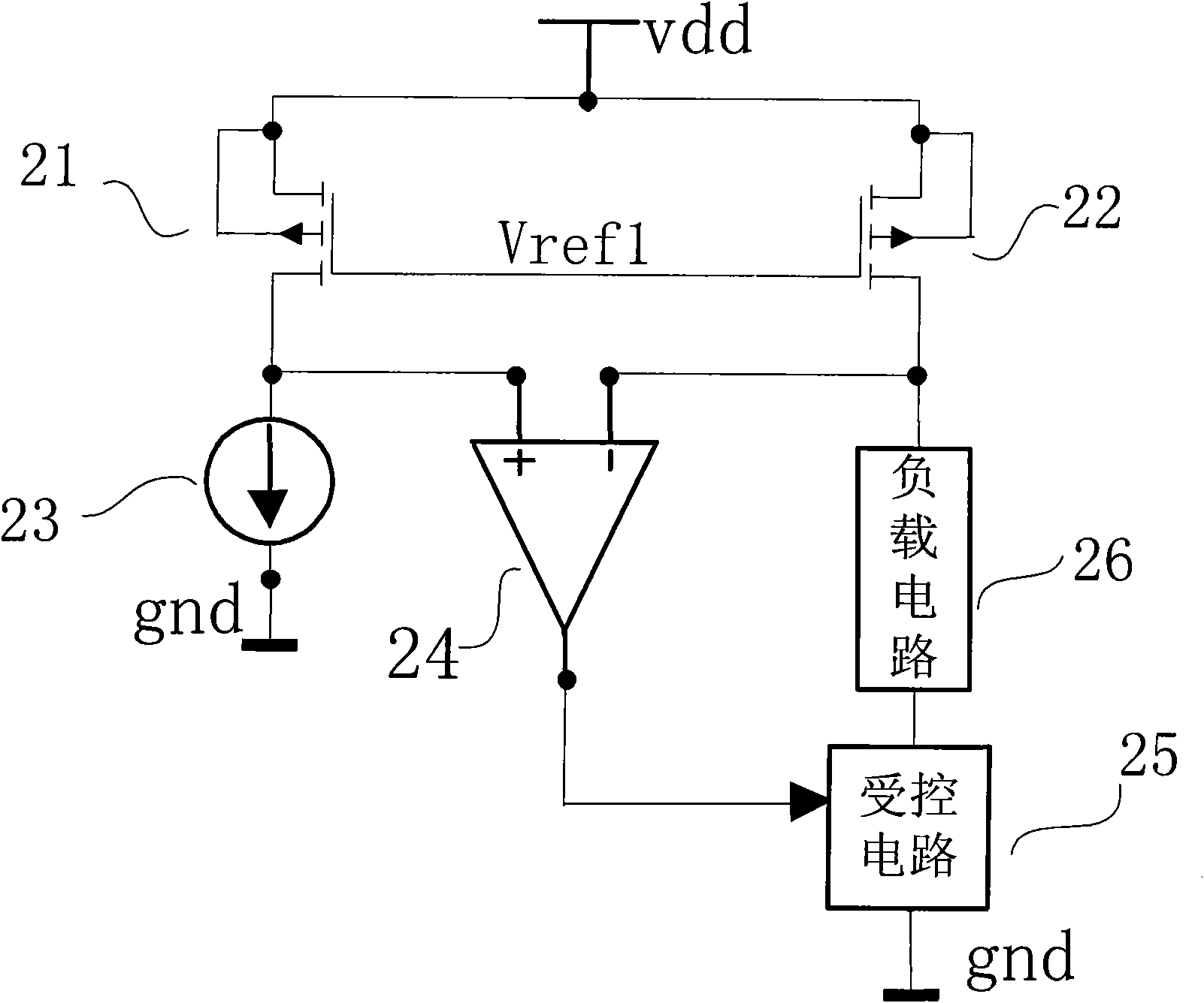
The invention discloses a matching current mirror for converting a current ratio and particularly relates to a current ratio converting current mirror for converting a reference current into an accurate fixed-fold current. The current mirror reduced current reproduction errors and ensures accurate current production. In the current mirror, the output end of an operational amplifier controls the current or voltage of a controlled circuit to change, so that a current or voltage signal generated after the change passes through a load circuit to generate a voltage value equal to that of the voltage at the positive input end of the operational amplifier at the negative input end of the operational amplifier. According to the characteristic that the voltage at the positive input end of the operational amplifier is equal to that at the negative input end of the operational amplifier, the drain voltages of two MOS tubes constituting the current mirror are clamped to be equalized so as to ensure that the drain-source voltages of the two MOS tubes constituting the current mirror are equal. The grid electrodes of the two MOS tubes constituting the current mirror are connected to ensure that the gate-source voltages of the two MOS tubes are equal. Thus, the current reproduction errors are reduced, the current is accurately reproduced, and the matching accuracy of the current mirror is improved.

Description

technical field [0001] The present invention relates to a current ratio conversion current mirror, in particular, it relates to a current ratio conversion current mirror for converting a reference current into an accurate fixed multiple current. Background technique [0002] It is well known that current mirrors are widely used in analog circuits. figure 1 The basic current mirror structure is shown. The ratio of the output current Io to the reference current Ir mainly depends on the ratio of the width to length ratio of the 12 tubes and the 11 tubes through which the current flows. It can copy the reference current in a certain proportion. However, the ratio of Io and Ir is also affected by their respective drain-source voltages. The drain and gate voltages of the M1 tube are equal, but the drain voltage of the 12 tube may be biased at any voltage according to needs, which causes errors in current replication. . Invention content: [0003] The content of the present inv...

Claims


Application Information

Patent Timeline
Patent Type & Authority Applications(China)
IPC IPC(8): G05F3/26
Inventor 曹先国
Owner 曹先国
Learn More