Permanent magnet synchronous motor

A synchronous motor and permanent magnet technology, which is applied to synchronous machines, synchronous motors for single-phase current, synchronous motors with stationary armatures and rotating magnets, etc. and other problems, to achieve the effect of high asynchronous torque, enhanced strength and low cost

Inactive Publication Date: 2010-01-20
PANASONIC CORP
View PDF5 Cites 10 Cited by
  • Summary
  • Abstract
  • Description
  • Claims
  • Application Information

AI Technical Summary

Problems solved by technology

[0007] When using that prior art permanent magnet with a squirrel-cage conductor, since the conductive rod and the permanent magnet are used as the driving element for rotation, if the conductive rod and the permanent magnet are not positioned correctly relative to each other, then the guide rod produces The force of the force and the force generated by the permanent magnet are opposite to each other, so that an effective rotational drive cannot be achieved
In addition, permanent magnets with such squirrel-cage conductors require complex and numerous manufacturing steps, since the permanent magnets and conducting rods are located inside the rotor

Method used


Image

  • Permanent magnet synchronous motor
  • Permanent magnet synchronous motor
  • Permanent magnet synchronous motor

Examples


no. 1 example

[0113] The first embodiment ( figure 1 with 2 )

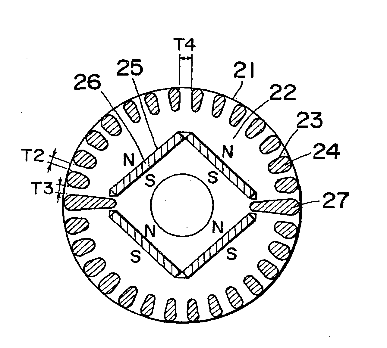
[0114] figure 1 is a cross-sectional view of a rotor for the self-starting synchronous motor using permanent magnets according to the first preferred embodiment of the present invention. In this figure, the rotor is indicated by reference numeral 21 and the rotor core is indicated by 22 . The rotor core 22 has a number of elongated holes 23 positioned on the outer circumference for accommodating a corresponding number of conducting rods 24 which are integrally cast together with a shorting ring (not shown) in any known die-casting aluminum technique. The axially spaced ends of the rotor core 22 thereby provide an actuating squirrel-cage conductor. The permanent magnets 26 are embedded in respective magnet holding holes, and the magnet holding holes are defined in the rotor core 22 and are located at one turn radially inside the conducting rod 24 .

[0115] exist figure 1 Within the range shown, two plate-shaped permane...

no. 2 example

[0146] The second embodiment ( image 3 )

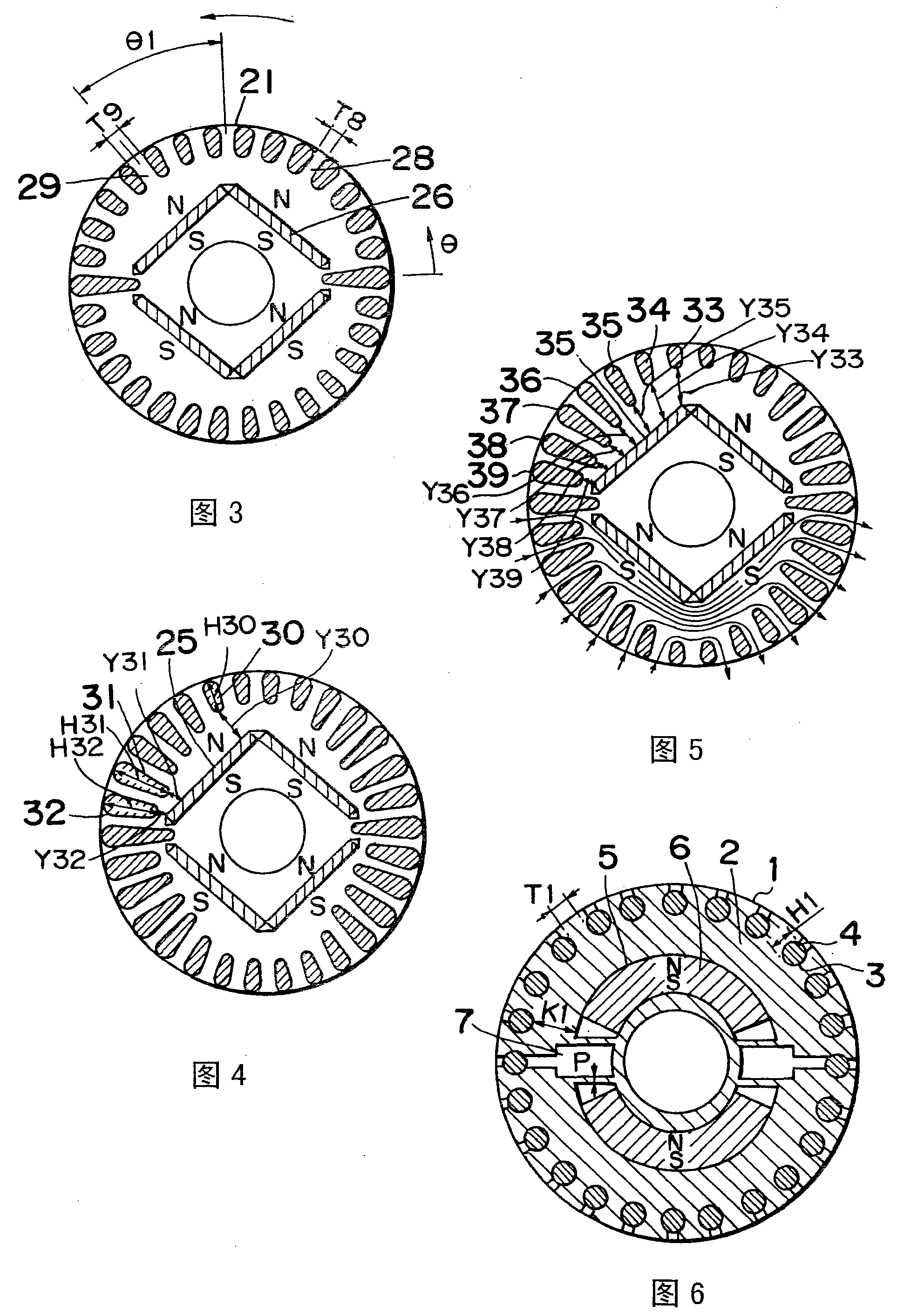
[0147] image 3 is a cross-sectional view of a rotor used in the self-starting permanent magnet synchronous motor according to the second preferred embodiment of the present invention. image 3 , the rotor 21 rotates in the direction indicated by the arrow. In operation under load, the combined magnetic flux of the magnetic flux emanating from the stator coil and the magnetic flux emanating from the permanent magnet 26 flows into the part 29 much more than the part 28. The part 29 is located along the rotor from the center of the rotor pole. Between adjacent long holes whose rotation direction is shifted forward by θ1. The portion 28 is located between two adjacent slots on the side offset from the center of the rotor pole to the rear. The size of the selected part 29, that is, the distance T8 between the two adjacent long holes on both sides of the part 29, is greater than the distance T9 between the adjacent long holes on the t...

no. 3 example

[0148] The third embodiment ( Figure 4 )

[0149] Figure 4 is a cross-sectional view of a rotor for a synchronous motor according to a third preferred embodiment of the present invention. Figure 4 Among them, one of the long holes 30 is located near the center of the rotor pole, and the long holes 31 and 32 are located near one of the two ends of the rotor pole. These elongated holes 30, 31, 32 have different radial lengths H30, H31 and H32 respectively, and the distances Y31 and Y32 between the elongated hole 31 and the magnet holding hole 25 and between the elongated hole 32 and the magnet holding hole 25 are smaller than Y30, Y30 is the distance between the elongated hole 30 and the magnet holding hole 25, from which the magnetic flux diverging to the permanent magnets near the outer peripheral surface of the rotor magnetic pole is almost very small, otherwise, it is scattered to the outer peripheral surface near the center of the rotor magnetic pole. For this reason,...


PUM


Abstract

The present invention provides a synchronous motor which comprises a stator including a stator iron core having a winding wound therearound and also having an inner cylindrical surface; a rotor including a rotor iron core in the form of a rotor laminate of a plurality of electromagnetic steel plates and rotatably accommodated while facing the inner cylindrical surface of the stator iron core, said rotor iron core including a magnet retaining portion provided with magnet retaining slots, a magnetic flux shortcircuit preventive portion coupled with the magnet retaining portion and provided with magnetic flux shortcircuit preventive holes communicated with the magnet retaining holes, and a rotor outer end portion coupled with the magnetic flux shortcircuit preventive portion and provided with holes communicated with the magnetic flux shortcircuit preventive holes; and permanent magnets embedded within the magnet retaining holes in the rotor and defining rotor magnetic poles. In this structure, the magnetic flux shortcircuit preventive holes are smaller than the magnet retaining holes such that by allowing the permanent magnets to be held in engagement with outer edges of the magnetic flux shortcircuit preventive holes, the permanent magnets are axially positioned.

Description

[0001] This application is a divisional application of the invention patent application filed by the applicant on December 30, 2004, with the application number 200410081814.9 and the invention name "Permanent Magnet Synchronous Motor". technical field [0002] The present invention relates generally to a permanent magnet synchronous motor, and more particularly to a synchronous motor commonly used in electric compressors of refrigeration or air conditioning systems or any other industrial electrical installation. Background technique [0003] Self-starting permanent magnet synchronous motors can be operated as an induction motor or as a synchronous motor, as an induction motor the starting is due to a starter squirrel-cage conductor, as a synchronous motor the rotating poles generated by the permanent magnets are formed by the stator coils Driven by the rotating magnetic field of the rotor, it rotates at an approximate synchronous speed that the rotor can reach. The synchro...

Claims


Application Information

Patent Timeline
Patent Type & Authority Applications(China)
IPC IPC(8): H02K21/12H02K21/46H02K1/27H02K1/22H02K19/10
Inventor 佐佐木健治田村辉雄吉田三千宽滝本亨谷口英之上坂广幸
Owner PANASONIC CORP
Why Eureka
Try Eureka