Motor drive device
A driving device and motor technology, applied in electromechanical devices, control electromechanical transmission devices, motors, etc., can solve the problems of increased structural size, increased cost, difficulty in miniaturization and light weight
- Summary
- Abstract
- Description
- Claims
- Application Information
AI Technical Summary
Problems solved by technology
Method used
Image

Examples
Deformed example 1
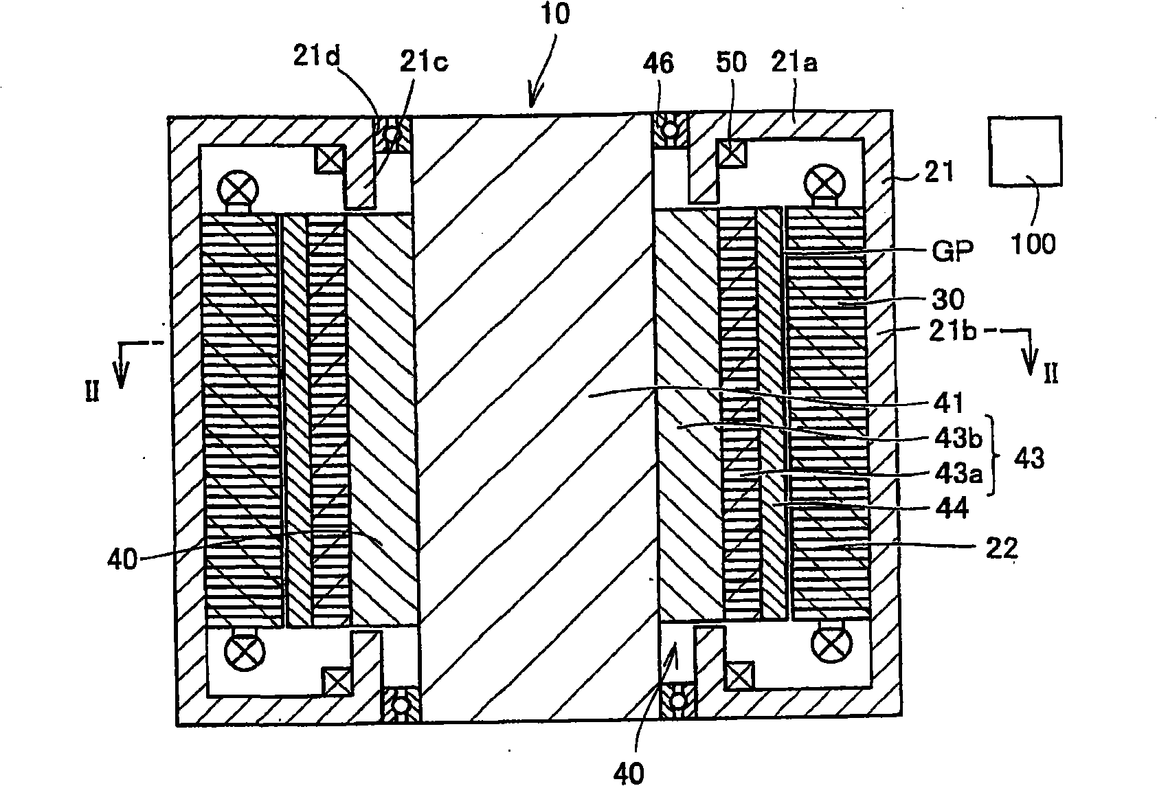
[0201] Figure 14 It is a side sectional view of the motor 11 of Modification 1 of the embodiment of the present invention, Figure 15 yes Figure 14 Sectional drawing of line XV-XV.
[0202] Such as Figure 15 As shown, the magnet 44 includes: a magnet (first magnet) 44a; and magnets (second magnets) 44b and 44c provided adjacent to the magnet 44a. The magnets 44b, 44c are provided at both ends of the magnet 44a.
[0203] The magnetic poles of the magnet 44 a positioned on the outer surface side of the rotor core 43 are arranged differently from the magnetic poles of the magnets 44 b and 44 c positioned on the outer surface side of the rotor core 43 . In this way, since the magnets 44b and 44c are provided, the magnetic flux of the magnets 44b and 44c is added to the magnetic flux of the magnet 44a, so that the total magnetic flux of the magnet 44 is larger than that of the magnet 44a alone. Furthermore, the magnets 44 a , 44 b , and 44 c extend between both end portions...
Deformed example 2
[0206] Figure 16 It is a perspective view of a rotor 40 of a motor according to Modification 2 of the embodiment of the present invention.
[0207] refer to Figure 16 , On the outer surface of the rotor 40, a magnet 44d and a magnet 44e are provided.
[0208] The surface of the magnet 44d facing outward is an N pole. And, the surface opposite to this surface is the S pole. That is, the N pole and the S pole of the magnet 44d are aligned in the radial direction, and the magnet 44d extends from one end portion of the rotor 40 to the other end portion.
[0209] The length of the magnet 44e in the axial direction is shorter than that of the magnet 44d, and extends from one end of the rotor 40 to the center of the rotor 40 in the axial direction. And, the magnet 44e is provided so that the outer surface of the rotor 40 may cover the part located between the magnets 44d.
[0210] The surface of the magnet 44e facing outward is an S pole, and the magnetic pole of a polarity di...
Deformed example 3
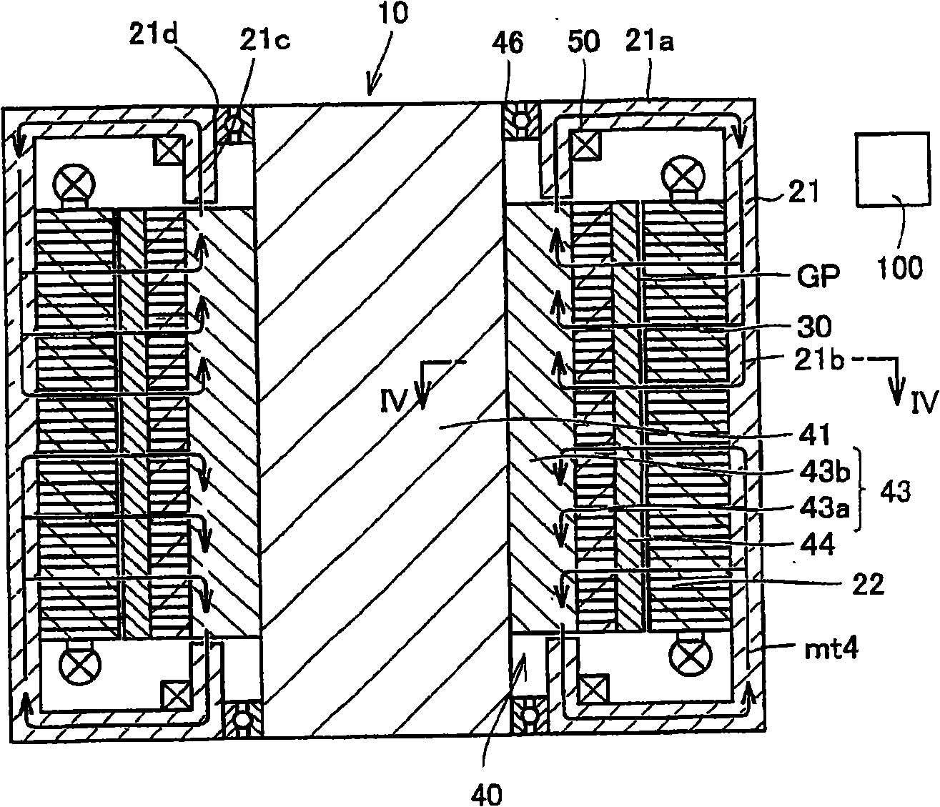
[0216] Figure 18 It is a side sectional view of the motor 14 of Modification 3 of the embodiment of the present invention, Figure 19 yes Figure 18 Sectional view of line XIX-XIX shown.
[0217] refer to Figure 18 , The motor 14 includes: a rotating shaft 41 ; a rotor 40 fixedly provided on the rotating shaft 41 ; a field yoke 21 provided on the outer periphery of the stator 30 ; and a field winding 50 .
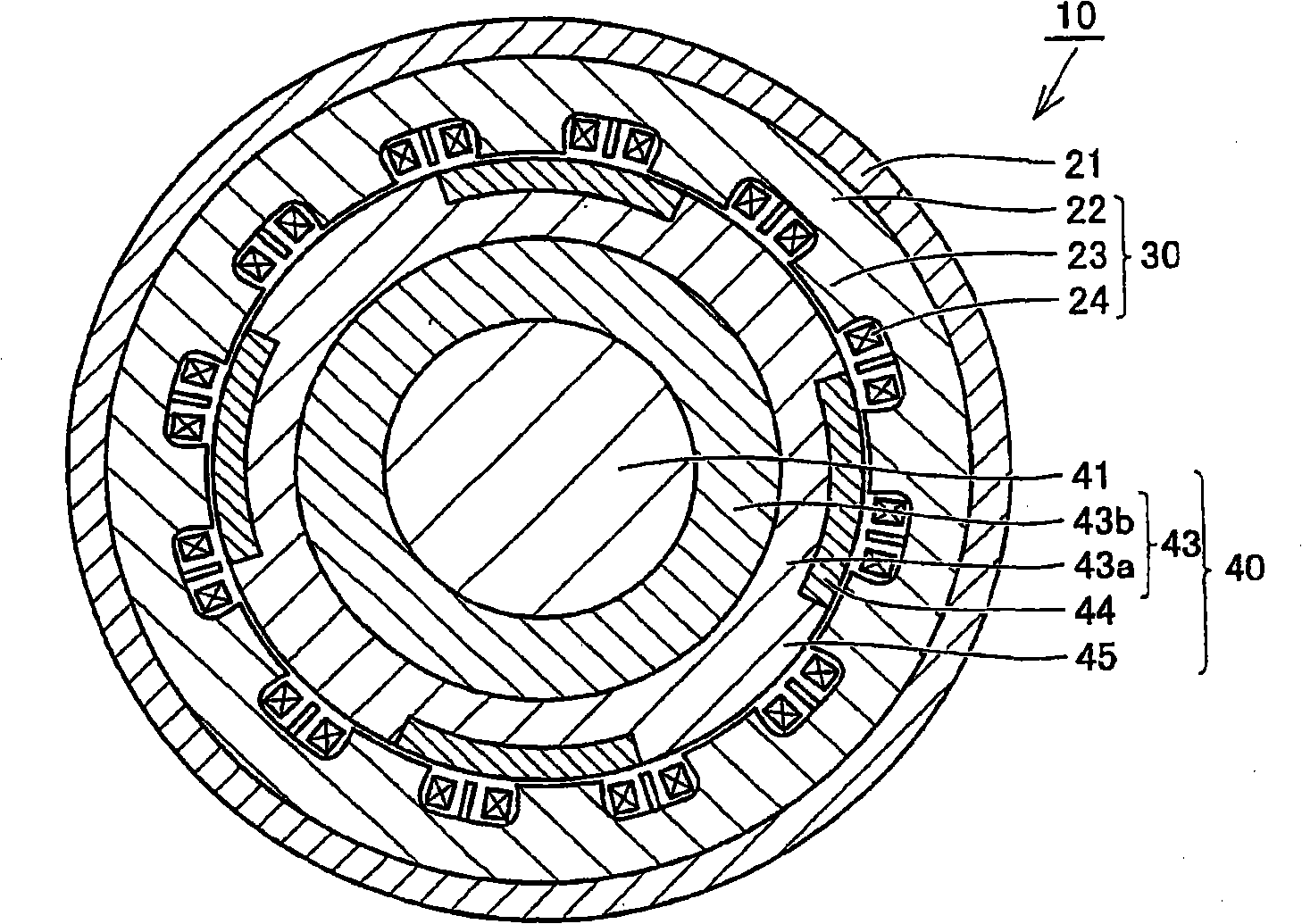
[0218] Such as Figure 19 As shown, the rotor 40 includes two rotor teeth 45 arranged opposite each other.
[0219] Preferably, the radial thickness t1 of the dust rotor core 43 b at the portion where the rotor teeth 45 are located is at least twice the radial thickness t2 of the dust rotor teeth 43 b at the portion located between the rotor teeth 45 .
[0220] In this way, by protruding the rotor teeth 45 in the radial direction, it is possible to suppress leakage of magnetic flux from the stator core 22 to the surface of the rotor core 43 located between the rotor ...
PUM
 Abstract
Description
Claims
Application Information
 - R&D
- Intellectual Property
- Life Sciences
- Materials
- Tech Scout
- Unparalleled Data Quality
- Higher Quality Content
- 60% Fewer Hallucinations
Browse by: Latest US Patents, China's latest patents, Technical Efficacy Thesaurus, Application Domain, Technology Topic, Popular Technical Reports.
© 2025 PatSnap. All rights reserved.Legal|Privacy policy|Modern Slavery Act Transparency Statement|Sitemap|About US| Contact US: help@patsnap.com