Distribution method and distribution device of mobile phases of chromatographic columns

A distribution method and a technology of a distribution device, which are applied in the field of mobile phase distribution in a chromatographic column, can solve the problems of reduced distribution uniformity, uneven initial fluid distribution, and influence on separation effect, so as to achieve easy clogging, easy cleaning and repeated use, The effect of simple structural design

Active Publication Date: 2010-01-27
BEIJING CHUANGXIN TONGHENG SCI & TECH
0 Cites 10 Cited by

AI-Extracted Technical Summary

Problems solved by technology

But for the larger chromatographic column of diameter, especially the diameter of the chromatographic column of existing industrial preparation chromatogram increases gradually, the distribution uniformity of the fine distribution channel after e...

Abstract

The invention discloses a distribution method and a distribution device of mobile phases of chromatographic columns. The distribution method comprises the steps: adopting a circular distributor matched with a cross section for preparing a chromatographic column; divergently arranging distribution liquid paths of liquid phases outwards in a tree shape along the center on the distributor; installing a distribution hole on the end of each distribution liquid path of liquid phases, wherein the lengths from the center of the distributor to the same-specification distribution liquid paths of liquid phases of all the distribution holes are equal; evenly distributing the liquid phases from the center of the distributor along each distribution liquid path of liquid phases to each distribution hole; and then evenly distributing the liquid phases to fixed phases of chromatographic columns. The distribution method can effectively eliminate the defect that the residence times of the mobile phases on a distribution system have serious differences along with the increase of the diameters of the chromatographic columns, can realize the even initial distribution of the mobile phases entering the chromatographic columns and can not be influenced by the high-pressure transport of the mobile phases. The distribution device has the advantages of simple structural design, difficult blockage, easy washing and repeated use.

Application Domain

Technology Topic

Image

  • Distribution method and distribution device of mobile phases of chromatographic columns
  • Distribution method and distribution device of mobile phases of chromatographic columns

Examples

  • Experimental program(1)

Example Embodiment

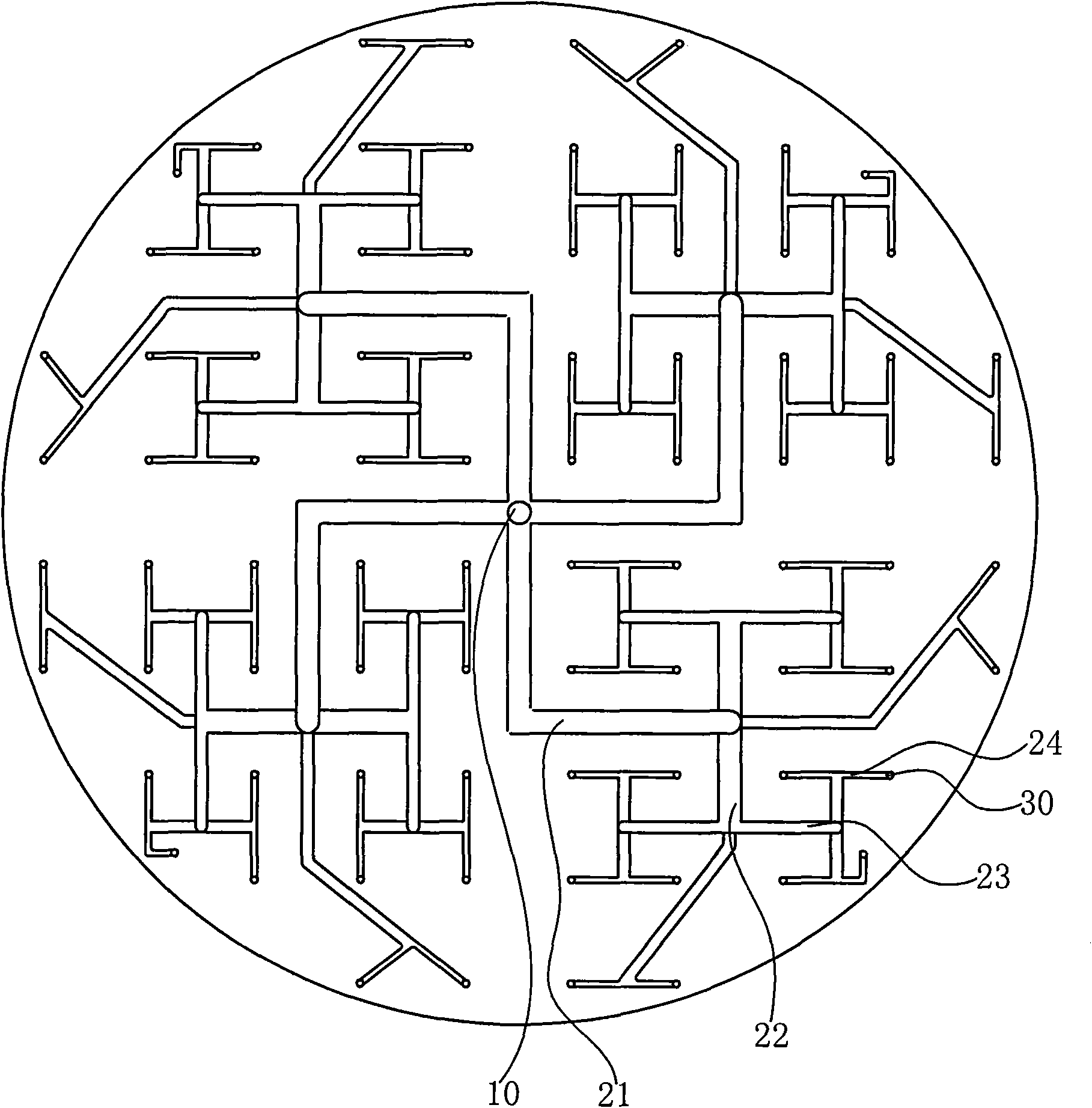
[0026] The mobile phase distribution method of the chromatographic column is used for the mobile phase distribution on the upper surface of the stationary phase in the preparation chromatographic column. It uses a circular distributor that matches the cross section of the preparation chromatographic column. The outer tree-shaped divergence is provided with a fluid phase distribution path, and the end of each fluid phase distribution path is provided with a distribution hole. The length of the same specification fluid phase distribution path from the center of the distributor to each distribution hole is equal; Distribute evenly from the center of the distributor to the distribution holes along each fluid phase distribution path, and then evenly distribute to the stationary phase of the chromatographic column. The liquid phase distribution path includes a plurality of first distribution paths diverging from the center to the outside. The end of the first distribution path is connected to the second distribution path, and the end of the second distribution path is further connected to the third distribution path. Then the third distribution fluid path continues to distribute to the subsequent lower-level distribution fluid paths. Wherein the distribution liquid flow of the second distribution liquid path is half of the first distribution liquid path, the distribution liquid flow of the third distribution liquid path is half of the second distribution liquid path, and each distribution hole is along the circle The rectangular distributors are arranged evenly distributed in a matrix, and the distribution liquid path connecting the two distribution holes and the other distribution liquid path connecting the distribution liquid path are arranged in an H shape.
[0027] In this way, the mobile phase can be uniformly, uniformly, and smoothly distributed to the upper surface of the stationary phase in the preparation chromatographic column within the flow range of 20-80L/min, and it can flow through the column bed evenly, uniformly and smoothly.
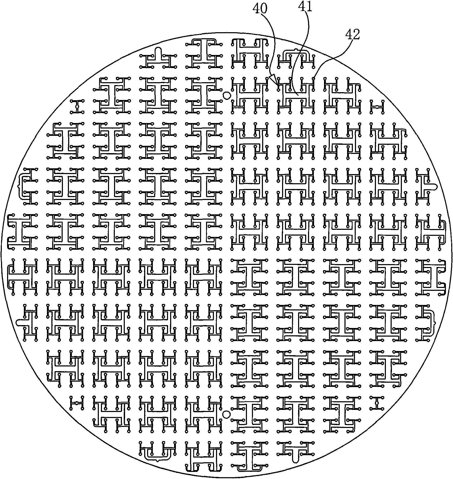
[0028] For the mobile phase distribution of a chromatographic column with a larger diameter, a secondary distributor can be further used, the secondary distributor is arranged at the lower part of the circular distributor, and the distribution units are distributed on the secondary distributor, Each distribution unit includes a plurality of connected liquid distribution channels, and the ends of each distribution liquid channel are provided with micro-distribution holes, wherein the distribution liquid channels include multi-stage distribution liquid channels, and the middle of the distribution liquid channel with the largest distribution liquid flow rate is located at all Below a distribution hole of the circular distributor. The micro-distribution holes on the secondary distributor are evenly distributed in a matrix along the circular end surface of the secondary distributor; each distribution hole passes through the distribution liquid path and multiple micro distribution holes, and adjusts the liquid path ruler diameter of the distribution liquid path so that each The distribution liquid flow of the two micro distribution holes is equal.
[0029] Such as figure 1 As shown, the mobile phase distribution device is a circular distributor whose outer diameter matches the cross-section of the preparative chromatographic column. A fluid phase distribution path is arranged on the distributor along the center of the distributor to diverge outward, and each fluid The end of the phase distribution liquid path is provided with a distribution hole 30, and the length of the fluid phase distribution path of the same specification from the center 10 of the distributor to each distribution hole is equal. The bulk distribution liquid path includes a plurality of first distribution liquid paths 21 diverging from the center to the outside. The end of the first distribution path is connected to the second distribution path 22, and the end of the second distribution path is further connected to the third distribution path. The distribution liquid path 23, and then the third distribution liquid path is connected to the lower level distribution liquid path until the last level distribution liquid path 24. In order to realize the calculation simplification in the design, the circulation ruler diameter (and the flow cross-sectional area of ​​the mobile phase) of the next stage of the distribution fluid path connected to each stage of the distribution fluid path is one-half of the distribution fluid path of the stage. The distribution holes are arranged evenly distributed in a matrix along the circular distributor, and a distribution liquid path that partially connects the two distribution holes and the other distribution liquid path that connects the level of the distribution liquid path is H-shaped.
[0030] Such as figure 2 As shown, the mobile phase distribution device may further include a secondary distributor, the secondary distributor is a circular distributor, the secondary distributor is provided with distribution units 40 distributed, each distribution unit includes a plurality of There are connected distribution liquid paths 41, and the ends of each distribution path are provided with micro-distribution holes 42. The distribution path includes a multi-level distribution path. The middle of the distribution path with the largest distribution liquid flow is located at one of the circular distributors. Below the distribution hole. The high-pressure mobile phase enters from the center hole of the distributor, and after several distributions, it flows out from the distribution hole at the same time, uniformly, and smoothly, and then passes through the secondary distributor again for simultaneous, uniform, uniform, and stable distribution.
[0031] In the present invention, regardless of the distributor or the secondary distributor, the expansion length of the liquid distribution path from the liquid receiving position to the distribution hole or the micro distribution hole is correspondingly equal, and the cross-sectional area of ​​the distribution liquid path of all levels decreases during each distribution. , Is one-half of the distribution liquid path of the upper level to ensure that the mobile phase flows at a medium speed in the distribution liquid path.

PUM

no PUM

Description & Claims & Application Information

We can also present the details of the Description, Claims and Application information to help users get a comprehensive understanding of the technical details of the patent, such as background art, summary of invention, brief description of drawings, description of embodiments, and other original content. On the other hand, users can also determine the specific scope of protection of the technology through the list of claims; as well as understand the changes in the life cycle of the technology with the presentation of the patent timeline. Login to view more.

Similar technology patents

Classification and recommendation of technical efficacy words

  • Simple structural design
  • Not easy to block

Waste lead acid battery crusher

InactiveCN101797526ANot easy to blockImprove work efficiencyLead-acid accumulatorsReclaiming serviceable partsCrusherMechanical field
Owner:ZHEJIANG HUITONG POWER

High-quality spray absorber for wet flue gas desulfurization

ActiveCN102764582AOvercomes easy crystallization and scalingNot easy to blockDispersed particle separationGypsumSulfur dioxide
Owner:武汉华德环保工程技术有限公司
Why Eureka
Try Eureka