
Method and mechanism for controlling deflection angle of blade of vertical axis wind turbine

A wind turbine blade and angle control technology, which is applied to the control of wind turbines, wind turbines at right angles to the wind direction, wind turbines, etc., can solve the problems affecting the wind energy utilization coefficient of wind turbines, the difficulty of wind turbine maintenance, slider lubrication and Sealing troubles and other problems, to achieve the effect of increasing the utilization coefficient of wind energy, easy processing and installation, easy lubrication and sealing

Inactive Publication Date: 2010-01-27
曹连
View PDF2 Cites 6 Cited by
  • Summary
  • Abstract
  • Description
  • Claims
  • Application Information

AI Technical Summary

Problems solved by technology

[0003] Since the swing range of the blades is limited by the slider and the stop rod, the blades and related components are in a state of frequent collision during operation, which is easy to cause damage to the components, and the lubrication and sealing of the sliders are also troublesome, which brings difficulties to the maintenance of the wind turbine. , because the wind turbine works in an open-air environment, and the main moving parts are suspended in mid-air
At the same time, frequent impacts will also bring noise
[0004] When the wind rotor is running, when the blade swings to the limit range of the block, it is in a completely downwind state (zero lift angle of attack), and the blade does not generate lift. When the limit range is large, the zero lift angle of attack range of the wind rotor is also relatively small Large, it will affect the wind energy utilization coefficient of the wind turbine

Method used


Image

  • Method and mechanism for controlling deflection angle of blade of vertical axis wind turbine
  • Method and mechanism for controlling deflection angle of blade of vertical axis wind turbine
  • Method and mechanism for controlling deflection angle of blade of vertical axis wind turbine

Examples


Embodiment Construction

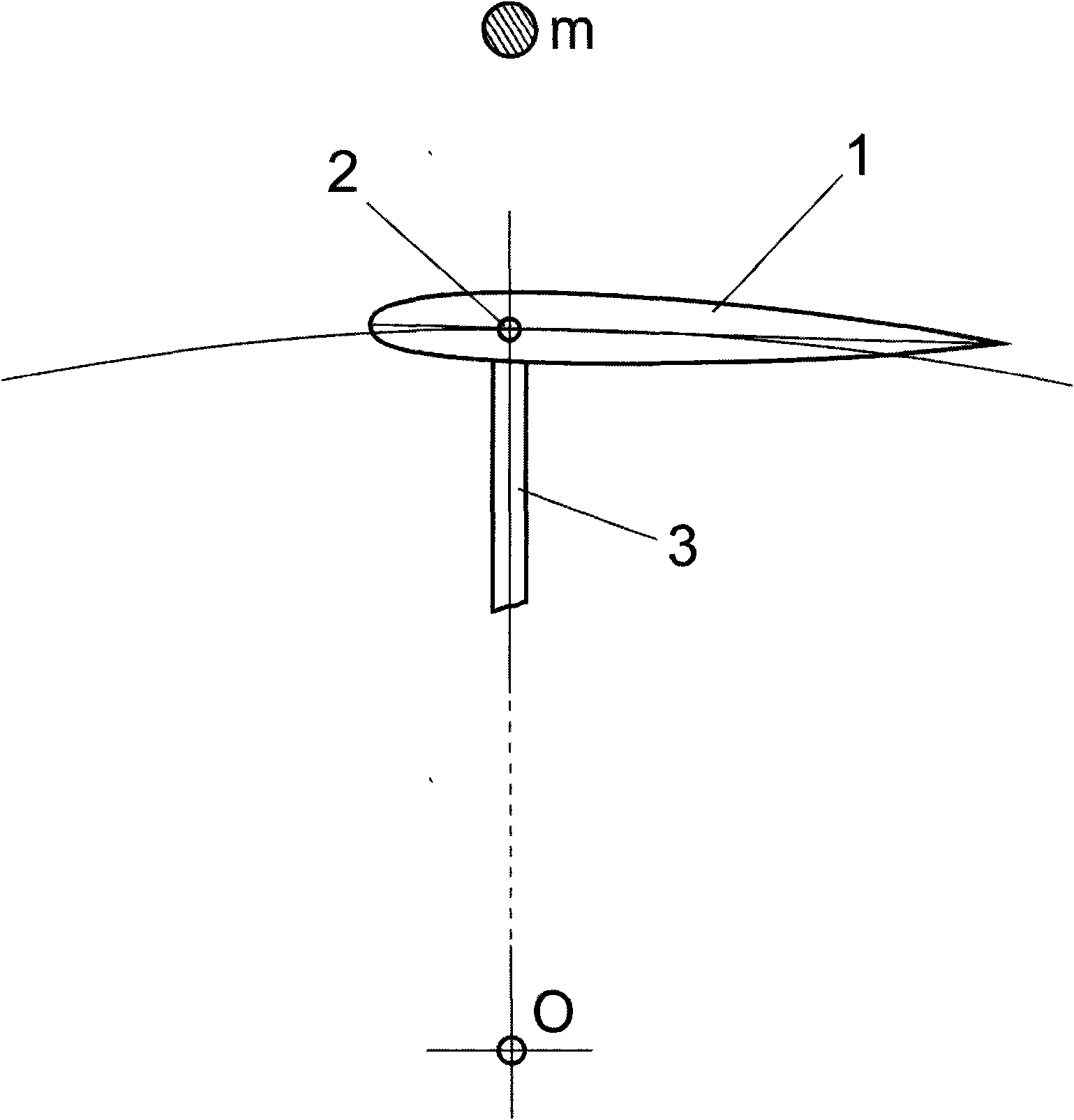
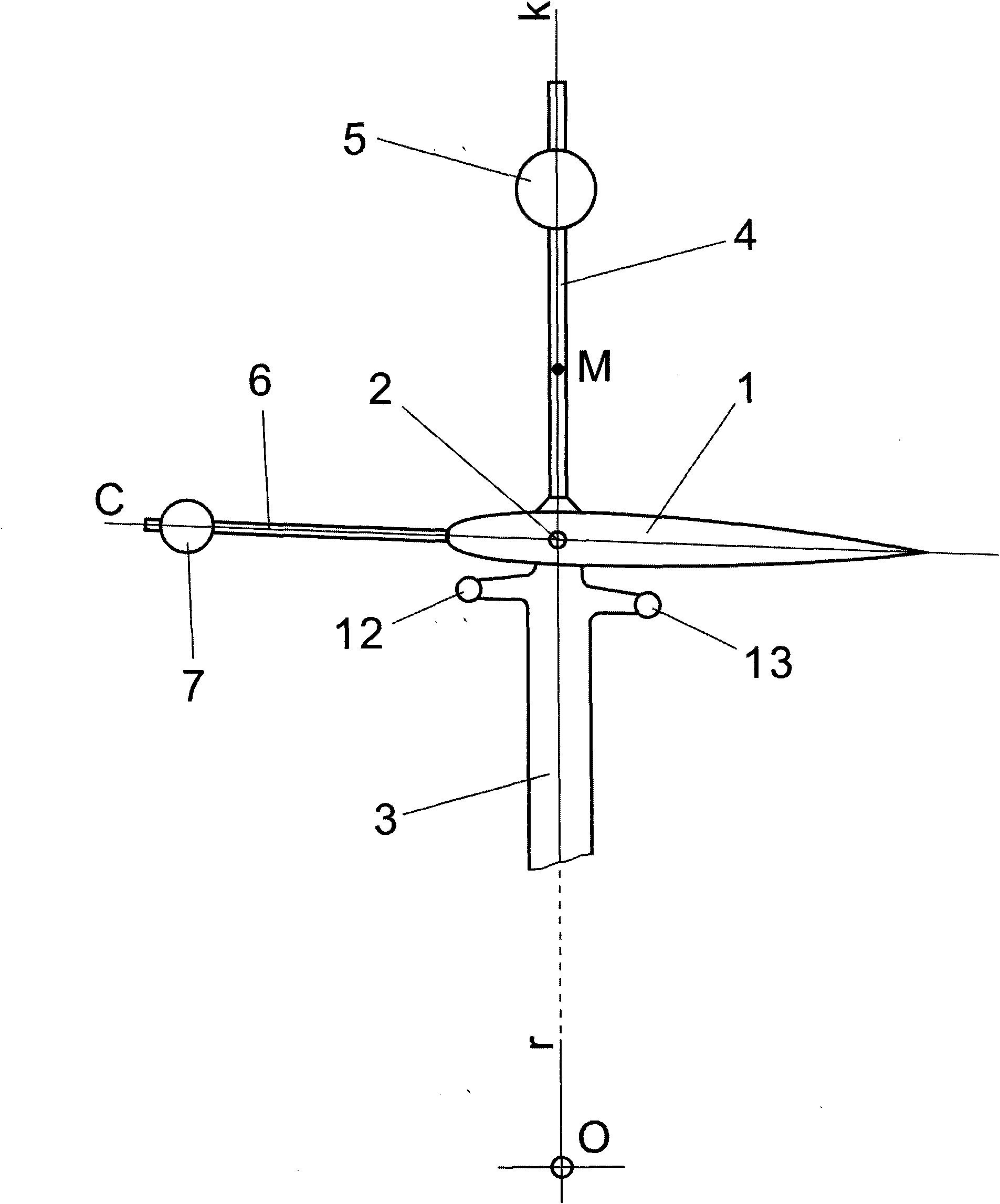
[0039] The blade 1 of the pendulum control mechanism for controlling the yaw angle of the vertical axis wind turbine blade of the present invention adopts a symmetrical airfoil. The blade 1 has a blade shaft 2 whose axis is parallel to the length of the blade and is the same as the axis of the central shaft O of the wind turbine. On a plane r. The position of the blade shaft 2 is as close as possible to the middle arc line of the blade (the middle arc line of the symmetrical airfoil coincides with the blade chord line), and the blade shaft 2 is in front of the pressure center of the blade (the symmetric airfoil can be selected at 1 / 4 of the leading edge of the blade Chord length forward position), the blade 1 is installed on the wind turbine bracket 3 through the blade shaft 2, and the blade 1 can rotate around the blade shaft 2, see figure 1 , image 3 .

[0040] The vertical axis wind turbine blade yaw angle control mechanism of the present invention adopts the position of the ...


PUM


Abstract

The invention discloses a method for controlling the deflection angle of a blade of a vertical axis wind turbine. A blade (1) is arranged on a wind wheel bracket (3) and can swing around a blade rotating axis (2); a component (9) is arranged at one side of the blade (1) towards the outside of the wind wheel and connected with the blade (1) to form a swing control member; when the wind turbine operates, the centrifugal force borne by the mass center (M) of the swing control member and the wind force borne by the blade (1) act together on the swing control member and enable the blade (1) to swing to a position where two moments are balanced. By properly choosing the mass of the mass center (M) or the position of the mass center (M) relative to the blade rotating axis (2), the wind wheel can operate according to the proper control parameters of the blade deflection. The invention also discloses four swing control mechanisms using the method for controlling the deflection angle of the blade.

Description

Technical field [0001] The invention relates to a method for controlling the angle of attack of a lift type vertical axis wind turbine blade. The angle of attack of the blade is adjusted by controlling the yaw of the blade, so that the performance of the lift type vertical axis wind turbine is greatly improved. The vertical axis of the invention relates to The wind turbine blade yaw mechanism uses centrifugal force and wind to directly control the blade yaw. Background technique [0002] The lift-type vertical axis wind turbine realizes the self-starting of the wind turbine through the yaw of the blades, can operate in a wide wind speed range, and also improves the wind energy utilization coefficient of the wind turbine. A simple and practical technology is to directly push the blade yaw by wind, and use a stopper to limit the yaw amplitude. In the Chinese invention patent application examination specification CN 1009569B, a swing-wing vertical axis wind turbine is disclosed. Th...

Claims


Application Information

Patent Timeline
Patent Type & Authority Applications(China)
IPC IPC(8): F03D7/06F03D3/06
CPCY02E10/723Y02E10/74
Inventor 曹连芃
Owner 曹连
Learn More