

Optical pulse raster distributed fiber sensing device
A technology of distributed sensing and sensing device, applied in the direction of using optical device, measuring device, using optical device to transmit sensing components, etc., can solve the difficulty of precise control of pulse gating, complex data processing equipment, low spatial resolution, etc. problem, to achieve the effect of fast sampling speed, strong anti-interference ability and high sensitivity
Inactive Publication Date: 2011-01-05
CHONGQING UNIV OF TECH
View PDF0 Cites 0 Cited by
- Summary
- Abstract
- Description
- Claims
- Application Information
AI Technical Summary
Problems solved by technology
Its shortcomings are: extremely high requirements on light source (high coherence and high stability), low spatial resolution, long measurement (cumulative average) time, difficult precise control of pulse gating, and complex data processing equipment
Method used
View moreImage
Smart ImageViewing Examples

Examples
Embodiment 1
Embodiment 2
Embodiment 3
Login to View More PUM
 Abstract
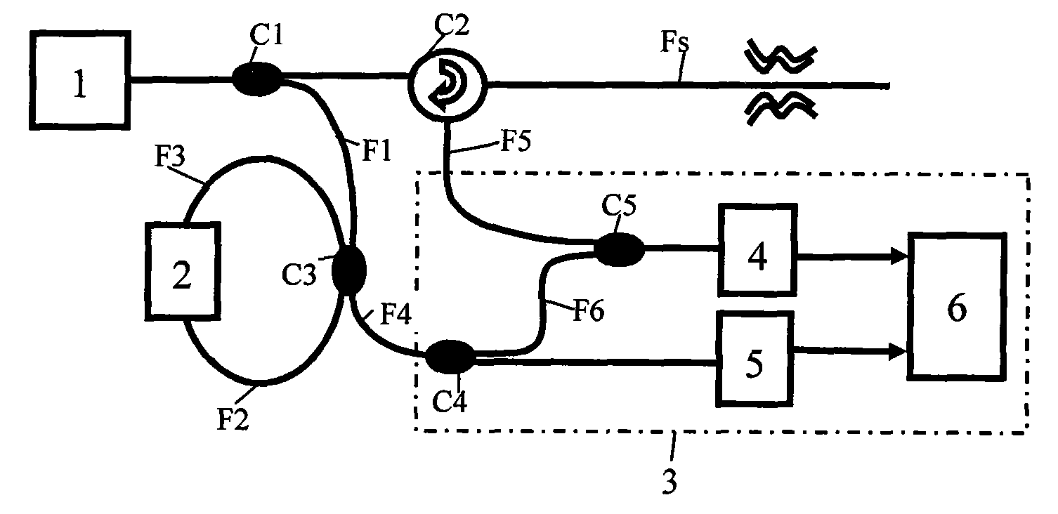
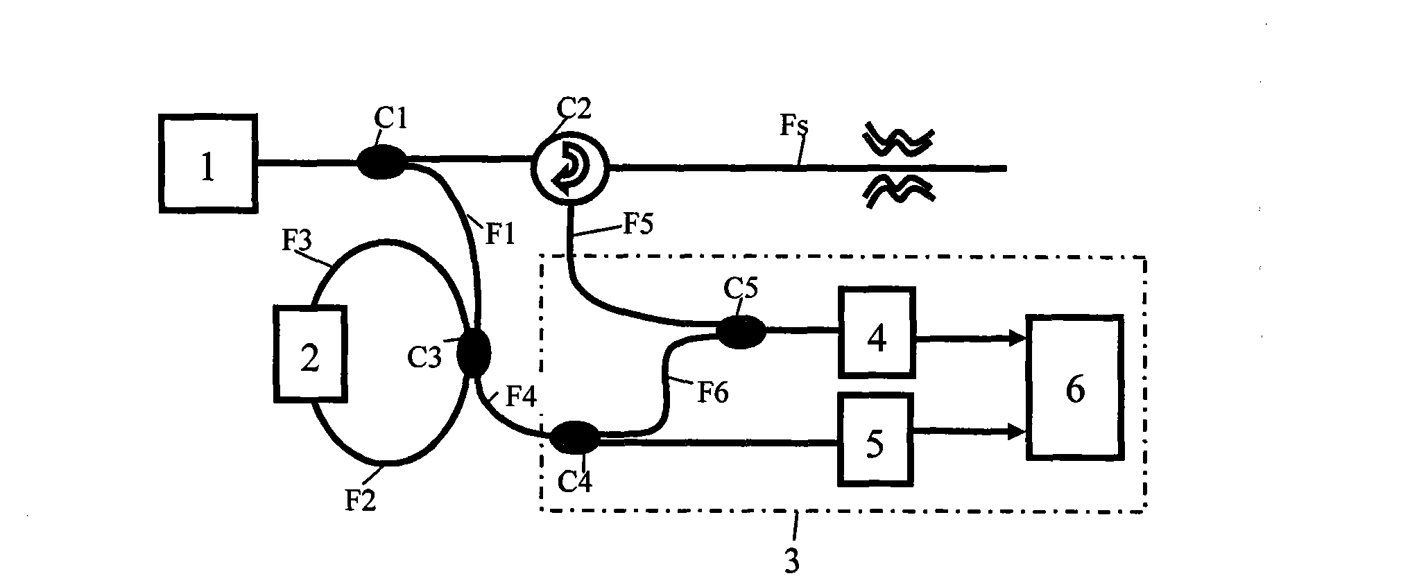
The invention discloses an optical pulse raster distributed fiber sensing device. The device comprises a low coherence pulse light source, an optical splitter, an optical circulator, an optical coupler, an optical amplifier, an optical interference device and sensing fibers. The low coherence pulse light source in the device is divided by the optical splitter into two beams, wherein one output beam is transmitted to the optical coupler; the optical coupler and the optical amplifier generate a pulse raster; the other output beam is transmitted to the sensing fibers by the optical circulator; and scattered light of the sensing fibers interferes with the pulse raster in the optical interference device and samples interference signals according to a time sequence to acquire distribution information. The device has the advantages of high sensitivity, low coherence requirement, rapid sampling, single circuit, and the like, can be used for the distribution detection of temperature, strain / stress, vibration, and the like of oceans, geologic structures, building structures, and the like, and can be also used for the tomography of oceans, atmosphere, biological tissue or other chemical or physical distribution substances, and the like, thereby having wide application range.
Description
Fiber Grating Distributed Sensing Device technical field The invention belongs to the technical field of fiber optics and fiber distribution sensing, and particularly relates to a fiber pulse grating distribution sensing device. Background technique Geology, large-scale structures and buildings such as oil wells, high-voltage power grids, mines, tunnels, bridges, water conservancy projects, aircraft, etc., require distributed monitoring of their stress / strain / deformation, vibration, temperature and other parameters to determine their (safe) state or prevent fires. The acquisition of these large-scale distributed field quantity information requires highly sensitive and high-precision distributed sensing devices to achieve effective monitoring. The optical fiber-based distributed sensing device can detect the information distribution of stress / strain, vibration, temperature and other fields along the optical fiber in time and space, that is, optical fiber sensing can extract...
Claims
Login to View More Application Information
Patent Timeline
 Patent Type & AuthorityPatents(China)
IPC IPC(8): G01D5/26G01D5/353G01B11/16G01H9/00
Inventor曾祥楷
OwnerCHONGQING UNIV OF TECH