Optical pulse raster distributed fiber sensing device

A distributed sensing and sensing device technology, applied in the direction of using optical devices, measuring devices, and using optical devices to transmit sensing components, etc., can solve the difficulties of precise control of pulse gating, complex data processing equipment, low spatial resolution, etc. problem, to achieve the effect of fast sampling speed, strong anti-interference ability and high sensitivity

Inactive Publication Date: 2010-01-27
CHONGQING UNIV OF TECH
View PDF0 Cites 21 Cited by
  • Summary
  • Abstract
  • Description
  • Claims
  • Application Information

AI Technical Summary

Problems solved by technology

Its shortcomings are: extremely high requirements on light source (high coherence and high stability), low spatial resolution, long measurement (cumulative average) time, difficult precise control of pulse gating, and complex data processing equipment

Method used


Image

  • Optical pulse raster distributed fiber sensing device
  • Optical pulse raster distributed fiber sensing device
  • Optical pulse raster distributed fiber sensing device

Examples


Embodiment 1

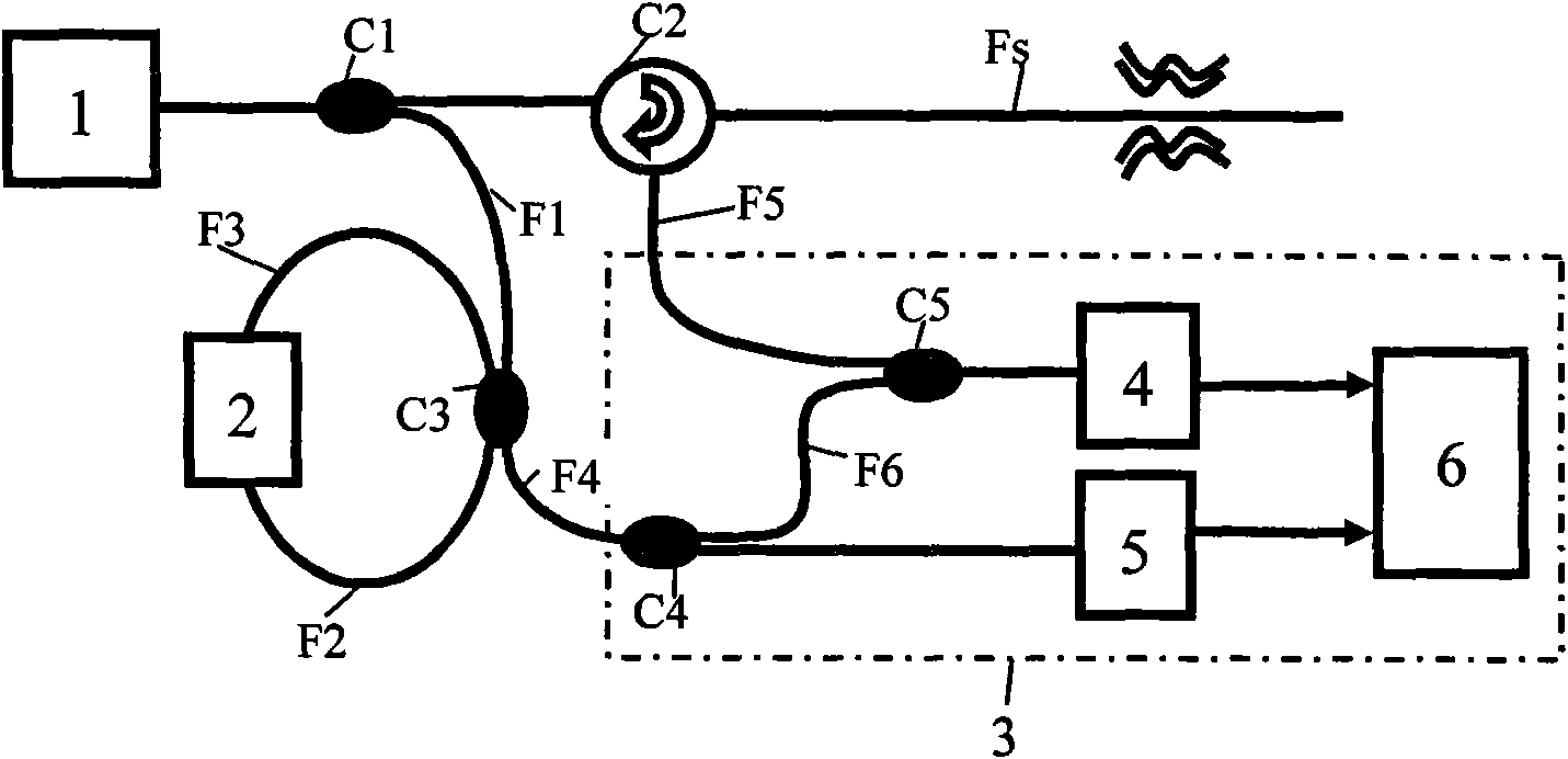
[0025] Embodiment one: see figure 2 , the structure of the optical fiber pulse grating distribution sensing device includes: a low-coherence pulsed light source 1, an optical splitter C1, an optical circulator C2, an optical coupler C3, an optical amplifier 2, and an optical interferometer 3; wherein the optical interferometer 3 includes Optical fiber splitter C4, optical fiber combiner C5, first photoelectric converter 4, second photoelectric converter 5 and data acquisition and processing system 6. The composition of this device is: (1) The low-coherence pulsed light source 1 is a pulsed light source with a central wavelength of 1550nm, a spectral bandwidth of 40nm, a pulse width of 20ns, a pulse energy of 15nJ, and a pulse repetition frequency of 1kHz, and an optical isolator is installed at its output end; The pulse light source is a pulse light source based on internal modulation, or a pulse light source based on a combination of a wide-spectrum light source and a light ...

Embodiment 2

[0028] Embodiment two: see image 3 The difference between the structure of the optical fiber pulse grating distribution sensing device and the structure of the first embodiment is: (1) in the present embodiment, the optical splitter C1 is a 1×2 polarization-maintaining fiber coupler with a coupling ratio of 90:10, The optical circulator C2 is a polarization maintaining fiber circulator or a 2×1 polarization maintaining fiber coupler, the optical coupler C3 is a 2×2 polarization maintaining fiber coupler with a coupling ratio of 50:50, and the optical amplifier 2 is a traveling wave semiconductor Optical amplifier, the isolation of optical splitter C1, optical circulator C2, and optical coupler C3 are all greater than 40dB; (2) in the present embodiment, the connection between the output end of optical splitter C1 and the input end of optical coupler C3 Fiber F1, the second output end of the optical circulator C2 and the connecting fiber F5 between the first input end of the o...

Embodiment 3

[0029] Embodiment 3: The composition of this optical fiber pulse grating distribution sensing device differs from that of Embodiment 1 in that the low-coherence pulsed light source 1 and the optical amplifier 2 are different: (1) In this embodiment, the low-coherence pulsed light source 1 is a femtosecond laser Light source or ultrashort pulse light source; The light pulse width of this femtosecond laser light source or ultrashort pulse light source is 300fs, center wavelength 800nm, spectral width 10nm, pulse energy is less than 1nJ, repetition frequency 1kHz; (2) in the present embodiment, light Amplifier 2 is a traveling wave semiconductor optical amplifier capable of amplifying 750-850nm wavelength light. The electrical signal output from the first photoelectric converter 4 and the second photoelectric converter 5 to the data acquisition and processing system 6 is an envelope distribution corresponding to the distributed reflected light of the sensitive material or the sens...


PUM


Abstract

The invention discloses an optical pulse raster distributed fiber sensing device. The device comprises a low coherence pulse light source, an optical splitter, an optical circulator, an optical coupler, an optical amplifier, an optical interference device and sensing fibers. The low coherence pulse light source in the device is divided by the optical splitter into two beams, wherein one output beam is transmitted to the optical coupler; the optical coupler and the optical amplifier generate a pulse raster; the other output beam is transmitted to the sensing fibers by the optical circulator; and scattered light of the sensing fibers interferes with the pulse raster in the optical interference device and samples interference signals according to a time sequence to acquire distribution information. The device has the advantages of high sensitivity, low coherence requirement, rapid sampling, single circuit, and the like, can be used for the distribution detection of temperature, strain / stress, vibration, and the like of oceans, geologic structures, building structures, and the like, and can be also used for the tomography of oceans, atmosphere, biological tissue or other chemical or physical distribution substances, and the like, thereby having wide application range.

Description

technical field [0001] The invention belongs to the technical field of optical fiber optics and optical fiber distribution sensing, and in particular relates to an optical fiber pulse grating distribution sensing device. Background technique [0002] Geology, large-scale structures and buildings such as oil wells, high-voltage power grids, mines, tunnels, bridges, water conservancy projects, aircraft, etc., need to monitor their stress / strain / deformation, vibration, temperature and other parameters in order to determine their (safety) status or prevent fires. The acquisition of these large-scale distributed field information requires highly sensitive and high-precision distributed sensing devices to achieve effective monitoring. Optical fiber-based distributed sensing devices can detect the information distribution of stress / strain, vibration, temperature and other fields along the optical fiber in time and space, that is, optical fiber sensing can extract large-scale fields...

Claims


Application Information

Patent Timeline
Patent Type & Authority Applications(China)
IPC IPC(8): G01D5/26G01D5/353G01B11/16G01H9/00
Inventor 曾祥楷
Owner CHONGQING UNIV OF TECH
Why Eureka
Try Eureka