Casting method of movable and fixed vortex casting pieces of compressor

A fixed vortex and casting technology, applied in the field of vortex casting, can solve the problems of molding equipment standby, narrow process range, and small solidification shrinkage, so as to relax the requirements of molten iron chemical composition and pouring temperature, and reduce production cost, the effect of eliminating hot joints in the dedendum

Inactive Publication Date: 2010-02-03
山西华翔同创铸造有限公司
View PDF0 Cites 19 Cited by
  • Summary
  • Abstract
  • Description
  • Claims
  • Application Information

AI Technical Summary

Problems solved by technology

[0002] The hot spot refers to the node or area where the casting is solidified slower than the surrounding metal during the solidification process. After the casting is solidified, shrinkage porosity and shrinkage cavity are easily formed at the hot spot. At present, the common methods to solve the shrinkage porosity and shrinkage cavity of the casting are: 1. The feeding riser is used alone. The main function of the riser is to compensate the liquid shrinkage of the molten metal in the cavity and the shrinkage of the casting during solidification, so as to obtain a dense casting without shrinkage cavity. When the casting is cooled in the mold, the thinnest The part of the body solidifies first, and its shrinkage can be compensated by the thicker part nearby; when the thicker part solidifies, it can be compensated by the thickest part; when the thickest part solidifies, if no external compensation is obtained, a large shrinkage will form there In this case, the role of the riser is to compensate for the last solidified part of the casting, so the riser is placed above or on the side of the thickest part of the casting, and its solidification is required to be later than the thickest part of the casting, the riser Feeding has a good feeding effect on concentrated hot spots near the center of the vortex, but for vortex castings, due to the limitation of feeding distance and feeding channel modulus, the feeding effect on concentrated hot spots near the center of the vo

Method used


Image

  • Casting method of movable and fixed vortex casting pieces of compressor
  • Casting method of movable and fixed vortex casting pieces of compressor
  • Casting method of movable and fixed vortex casting pieces of compressor

Examples


Example Embodiment

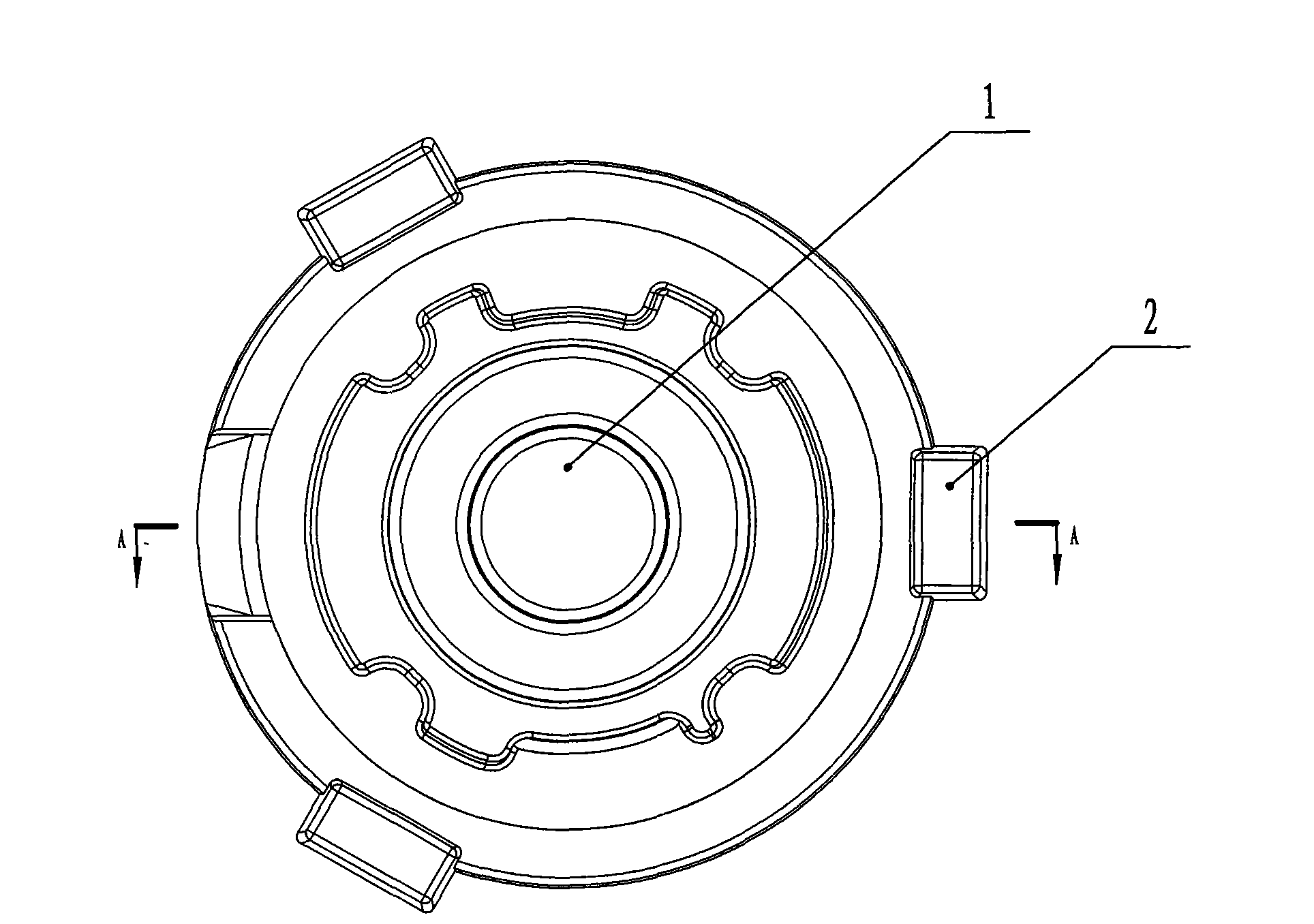
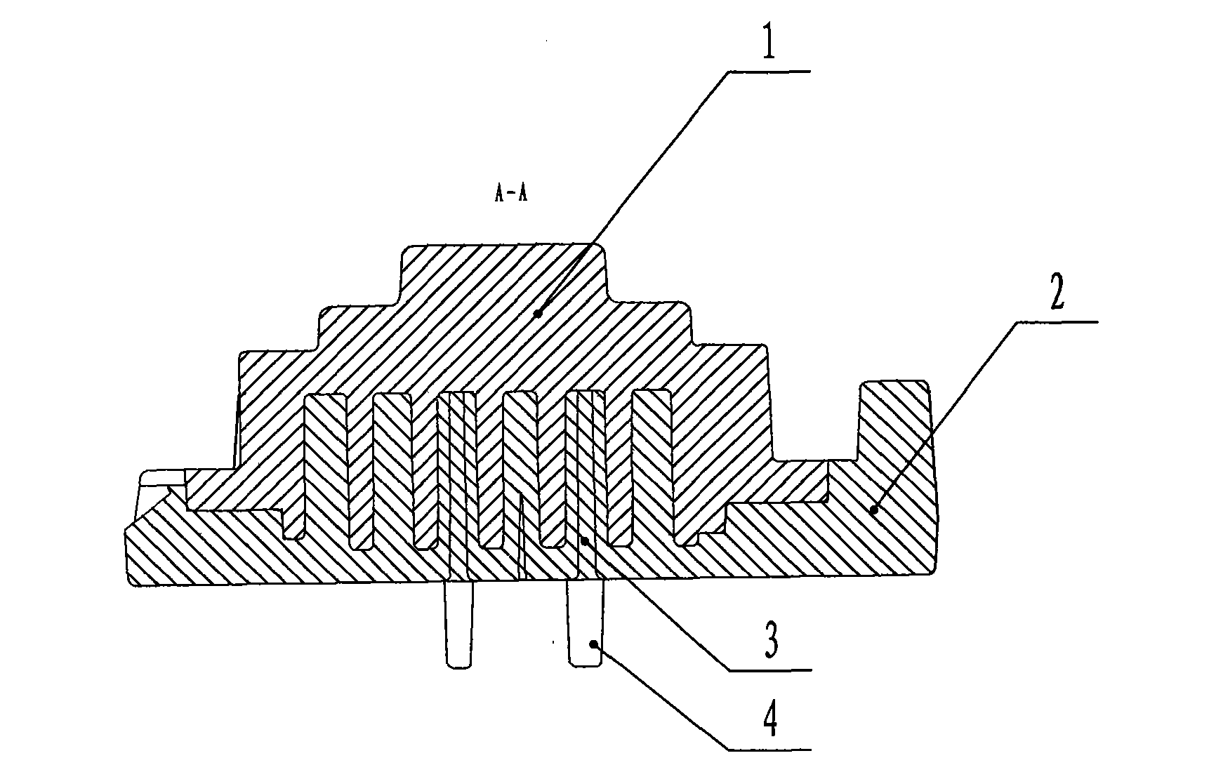
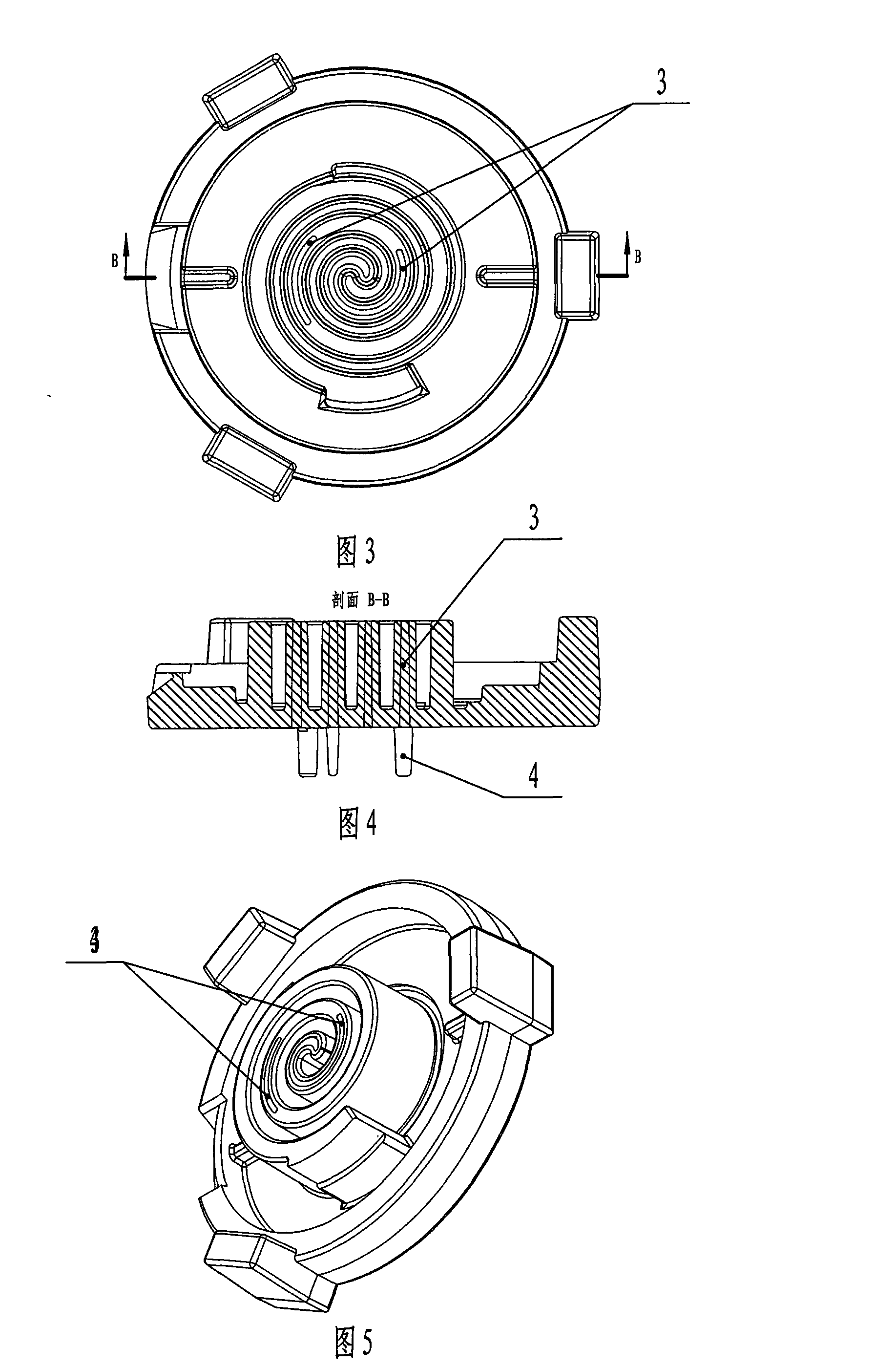
[0025] The invention discloses a method for casting compressor moving and fixed scroll castings. The conformal chilled iron 3 is embedded in the casting 1 at the corresponding position of the core box and then sand is shot to produce a sand core with conformable chilled iron 3. 2; Put the sand core 2 with the conformal cold iron 3 into the mold, and combine the feeder feeding process to cast the casting 1 (such as figure 1 , 2 Shown).

[0026] When the scroll casting is solidified, the sand core 2 sandwiched between the scroll teeth has a heat preservation effect and becomes the final solidification hot spot. The intersection of the moving and fixed scroll teeth roots and the chassis in the scroll compressor follows the vortex. There are narrow and long heat joints with closed loops in the direction, and the shrinkage porosity and shrinkage holes formed at these hot joints have a great influence on the mechanical properties of the casting 1 and bring great safety hazards to produc...


PUM


Abstract

The invention provides a casting method of movable and fixed vortex casting pieces of a compressor, aiming at solving the technical problem that the movable and fixed vortex casting pieces generate loosing and shrinkage at the hot joint in the casting process. The casting method comprises the following steps: embedding a conformal cold iron into the hot joint of the casting piece at the corresponding position of a core box, then carrying out sand shooting and manufacturing a sand core with the conformal cold iron; and placing the sand core with the conformal cold iron into a casting mold, combining a dead head feeding technique and casting the casting piece. The shape of the conformal cold iron is manufactured into a vortex shape or an arc shape according to the shapes of a vortex sand core teeth and the position of the hot joint of the vortex casting piece. One end of the conformal cold iron is provided with a columnar positioning lag; and the core box is provided with a positioning hole matched with the positioning lag. The sand core is internally provided with the conformal cold iron which is directly applied on the hot joint, thus having fast cooling speed and leading the hot joint position to obtain maximum subcooled temperature in the vortex casting piece. The casting method can effectively solve the defects of loosing and shrinkage of the root part of the vortex teeth.

Description

Technical field [0001] The invention relates to a casting method, in particular to a casting method of scroll castings. Background technique [0002] Hot joint refers to the node or area where the casting solidifies more slowly than the surrounding metal during the solidification process. After the casting solidifies, shrinkage porosity and shrinkage cavities are easily formed at the hot joint. At present, the common methods to solve the casting shrinkage porosity and shrinkage are: 1. The feeder is used alone. The main function of the feeder is to compensate for the liquid shrinkage of the molten metal in the cavity and the shrinkage during the solidification of the casting to obtain a dense casting without shrinkage. The thinnest casting is when it is cooled in the mold. When the thickest part is solidified first, its shrinkage can be compensated by the thicker part nearby; when the thicker part is solidified, it can be compensated by the thickest part; when the thickest part i...

Claims


Application Information

Patent Timeline
IPC IPC(8): B22D15/00
Inventor 赵红卫
Owner 山西华翔同创铸造有限公司
Why Eureka
Try Eureka