Supercharge Your Innovation With Domain-Expert AI Agents!

Transformer, bobbin bracket and backlight module using the transformer

A winding frame and transformer technology, applied in the direction of transformer/inductor core, transformer/inductor coil/winding/connection, components of lighting devices, etc., can solve the problems of tension adjustment cost, complex production process of transformer, and many Time and other issues

Inactive Publication Date: 2010-02-03
KUNSHAN GUANJIE ELECTRONICS
View PDF0 Cites 0 Cited by
  • Summary
  • Abstract
  • Description
  • Claims
  • Application Information

AI Technical Summary

Problems solved by technology

However, since the secondary winding is made of thinner wire and has more turns than the primary winding, it will take a lot of time and manpower to change the leakage inductance of the transformer, and the production process of the transformer will also change. quite complicated
In addition, due to the thinner wires of the secondary winding, it takes a considerable amount of time to adjust its tension

Method used


Image

  • Transformer, bobbin bracket and backlight module using the transformer
  • Transformer, bobbin bracket and backlight module using the transformer
  • Transformer, bobbin bracket and backlight module using the transformer

Examples


Embodiment 1

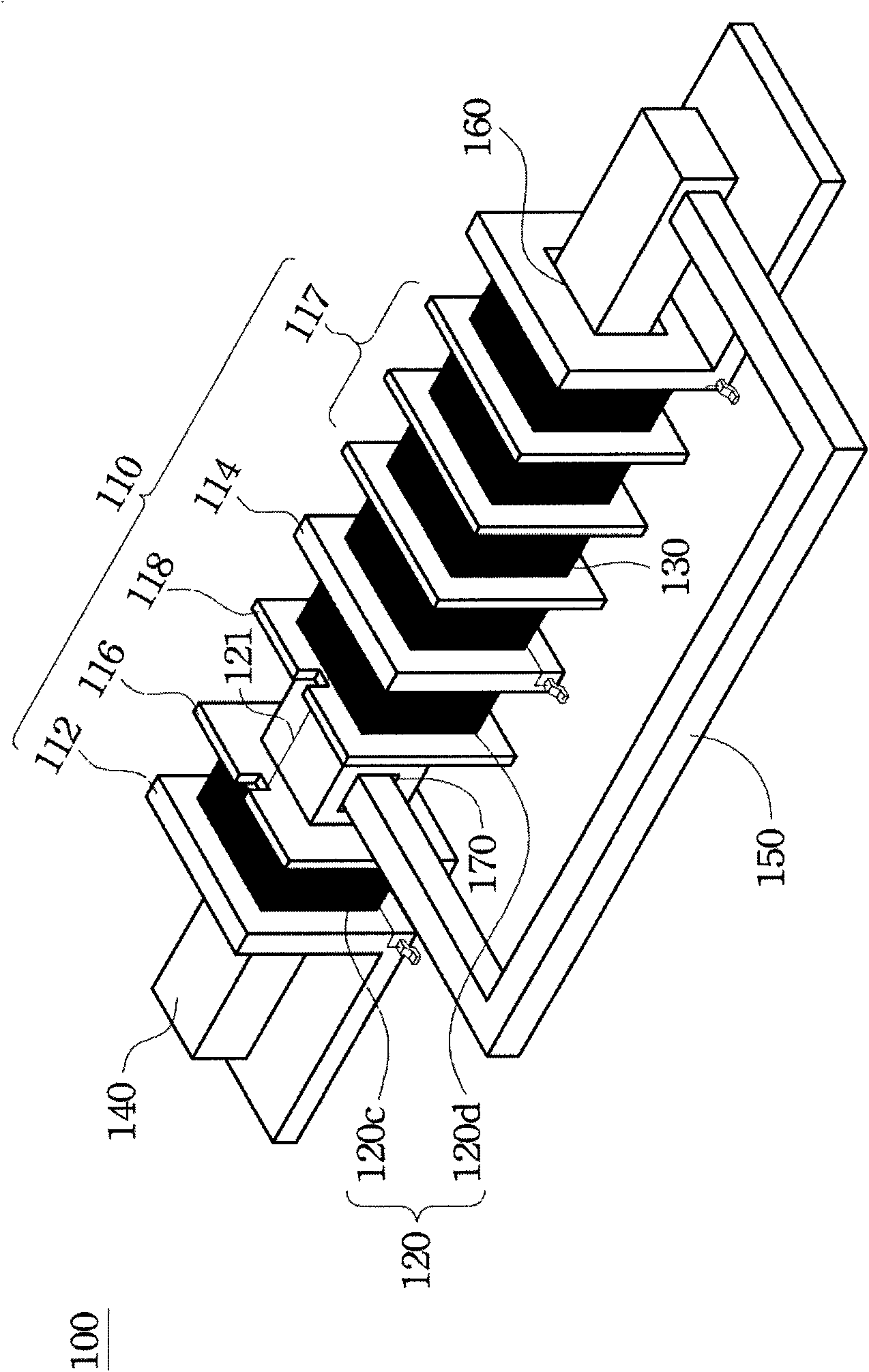
[0081] Embodiment one: see attached figure 1 , attached Figure 1A ,

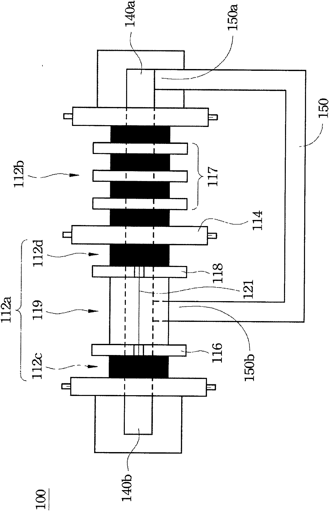
[0082] A transformer 100 includes a bobbin 110 , a primary winding 120 , a secondary winding 130 , and a first magnetic core 140 and a second magnetic core 150 . The bobbin frame includes a main body 112, a first partition 114, two second partitions 116, 118 and a partition 117, wherein the main body 112 is provided with an accommodating space in the axial direction for accommodating the first Magnetic core 140 . In this embodiment, the accommodating space is the through hole 160 passing through the main body 112 , and the first magnetic core 140 is placed in the through hole 160 passing through the main body 112 , but the invention is not limited thereto.

[0083]The first separator 114 is disposed on the main body 112 perpendicular to the axial direction of the main body 112 , and divides the main body 112 into a primary winding slot 112 a and a secondary winding slot 112 b. The separator 117 is locat...

Embodiment 2

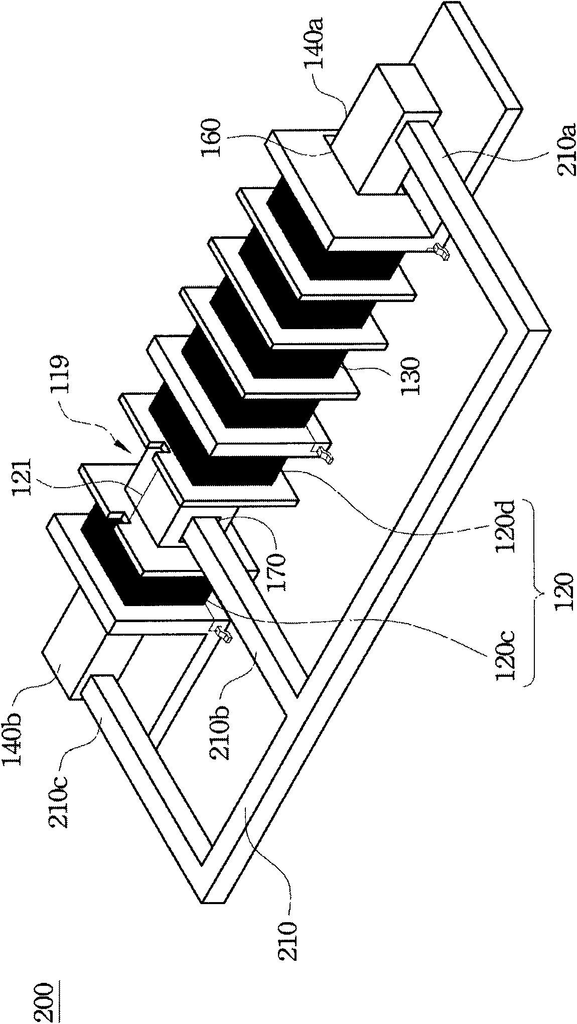
[0090] Embodiment two: see attached figure 2 as shown,

[0091] A transformer 200, which is different from the transformer 100 of Embodiment 1 in that: the second magnetic core is a magnetic core 210, which has three magnetic core ends 210a, 210b and 210c, wherein the magnetic core end 210b is inserted into To the first intervening space 119 , the magnetic core end 210 a is coupled to the magnetic core end 140 a of the first magnetic core 140 , and the magnetic core end 210 c is coupled to the magnetic core end 140 b of the magnetic core 140 . It can be known from the above description that the transformer 200 uses the magnetic core end 210c to couple with the magnetic core end 140b of the magnetic core 140 to change the magnetic circuit of the transformer 200 .

[0092] Others are the same as those in Embodiment 1, and will not be repeated here.

Embodiment 3

[0093] Embodiment three: see attached image 3 as shown,

[0094] A transformer 300, which differs from the transformer 100 in Embodiment 1 in that: the second magnetic core is a magnetic core 310, and the magnetic core 310 has three magnetic core ends 310a, 310b and 310c, wherein the magnetic core ends 310b is inserted into the first intervening space 119, the magnetic core end 310a is coupled to the magnetic core end 140a of the first magnetic core 140, and the magnetic core end 310c extends parallel to the axial direction of the bobbin. It can be known from the above description that the magnetic core end 310 c of the transformer 300 extends outward parallel to the axial direction of the bobbin, so as to change the magnetic circuit of the transformer 100 .

[0095] Others are the same as those in Embodiment 1, and will not be repeated here.


PUM


Abstract

The invention relates to a transformer, a bobbin bracket and a backlight module using the transformer. The transformer comprises the bobbin bracket, a primary winding, a secondary winding, a first magnetic core and a second magnetic core, wherein the bobbin bracket comprises a main body, a first partition plate and two second partition plates; the main body is provided with a containing space foraccommodating the first magnetic core; the first partition plate is arranged on the main body to partition the main body into a primary winding groove and a secondary winding groove; the second partition plates are arranged in the primary winding groove to partition the primary winding groove into a first primary winding sub-groove, a second primary winding sub-groove and intervention space; one end part of the second magnetic core is inserted into the intervention space, and the other end part is coupled with one end part of the first magnetic core. The invention can change a leakage inductance value by adjusting the distribution and the cycle of the primary winding in all the primary winding sub-grooves under the condition of fixing the cycle of the secondary winding, the change of the leakage inductance value can not influence the cycle of the secondary winding, thereby greatly simplifying the manufacture process of the transformer and then reducing the manufacture cost.

Description

technical field [0001] The invention relates to a transformer and its winding frame and a backlight module using the transformer, in particular to a transformer capable of providing high leakage inductance, its winding frame and the backlight module using the transformer. Background technique [0002] The backlight module is a component that can provide the back light source of the product. It is currently widely used in general consumer products such as various information and communications, such as: liquid crystal displays, slide viewing boxes, digital cameras, personal digital assistants (PDAs), surveillance devices and notebook computers. Most of the common liquid crystal display devices currently on the market are backlight liquid crystal displays. Such a liquid crystal display device generally mainly consists of a front-end liquid crystal display panel and a rear-end backlight module. Therefore, the backlight module is an optical component that provides the back lig...

Claims


Application Information

Patent Timeline
IPC IPC(8): H01F27/30H01F27/28H01F27/26F21V23/02
Inventor 张明宗吴东儒
Owner KUNSHAN GUANJIE ELECTRONICS
Features
  • R&D
  • Intellectual Property
  • Life Sciences
  • Materials
  • Tech Scout
  • Unparalleled Data Quality
  • Higher Quality Content
  • 60% Fewer Hallucinations
Learn More