PWM rectification type energy feedback device

An energy feedback and improved technology, which is applied in the direction of output power conversion device, AC power input conversion to DC power output, electrical components, etc., can solve the problem of only considering energy feedback power, increasing the electrical stress of the inverter, and filtering difficulties and other issues, to achieve the effect of reducing volume and switching noise, reducing current harmonic content, and reducing hardware complexity

Inactive Publication Date: 2010-02-03
盈威力新能源科技(上海)有限公司
View PDF0 Cites 12 Cited by
  • Summary
  • Abstract
  • Description
  • Claims
  • Application Information

AI Technical Summary

Problems solved by technology

[0002] In the existing full-control energy feedback device, its three core technologies, namely modulation technology, feedback energy power control, and synchronous detection, generally work in the following way: modulation is a random square wave pulse obtained by hysteresis loop comparison, The frequency is at the power frequency level and is not fixed, which makes filtering more difficult, and the low-frequency noise generated is extremely harmful to the human body; the energy feedback power only considers the amplitude of the voltage, and does not consider the continuous operation of the current, and the inverter is often on and off Intermittent conversion increases additional harmonic content and increases the electrical stress of the inverter; the synchronous detection is a hardware zero-crossing type detection, the circuit is complex and the accuracy is low; the defense against the DC current injected into the grid is basically not considered. When the DC component is injected into the grid due to uneven device characteristics or interference, it will cause the transformer at the grid end to be biased, and then generate abnormal heat, endangering the safety of the grid

Method used


Image

  • PWM rectification type energy feedback device
  • PWM rectification type energy feedback device
  • PWM rectification type energy feedback device

Examples


Embodiment Construction

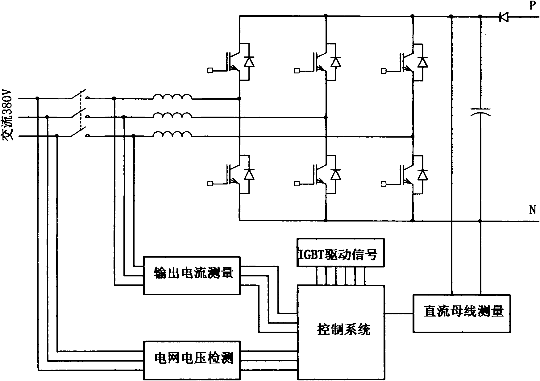
[0014] figure 1 As shown, the main circuit is composed of a three-phase bridge circuit, a grid voltage detection circuit, an output voltage direct detection circuit, a current detection circuit, a drive circuit, and a control circuit.

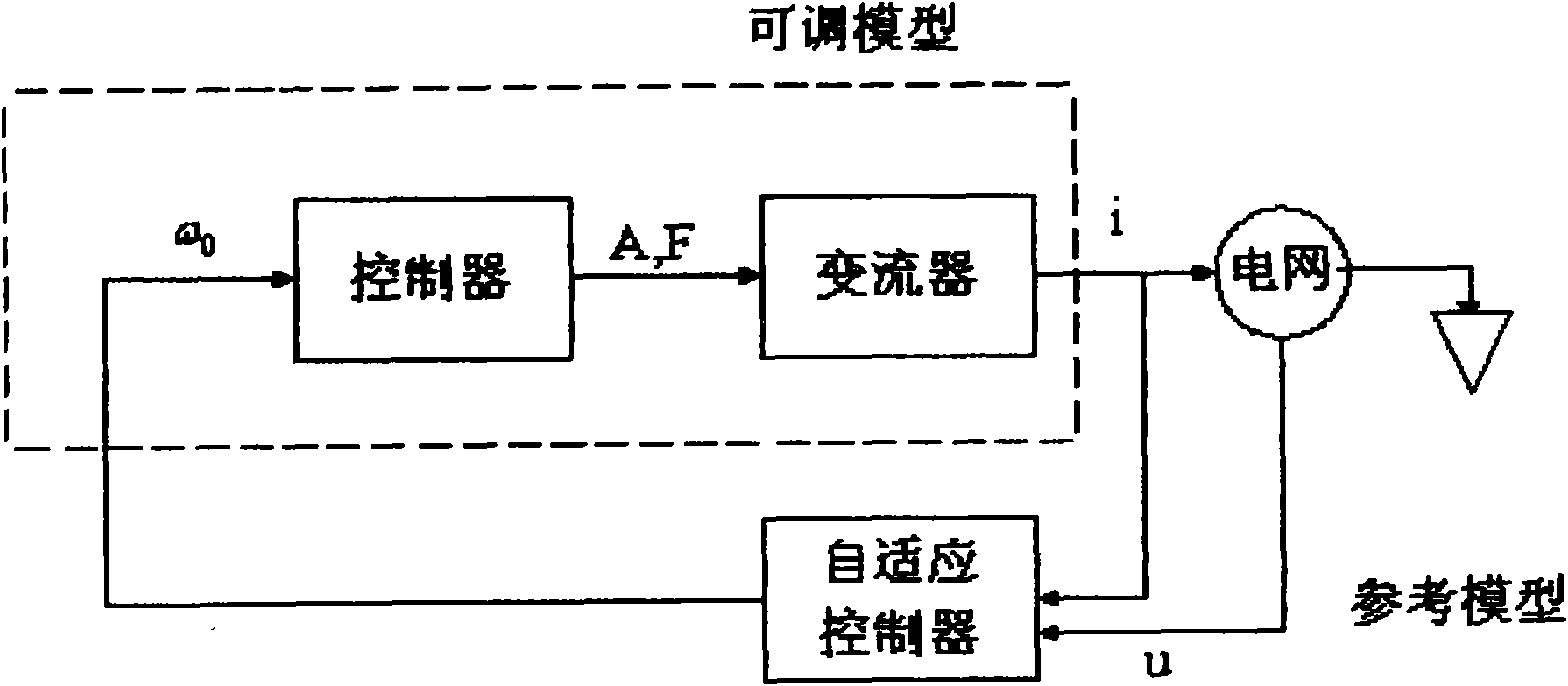
[0015] Such as figure 2 As shown, the phase-amplitude control is based on the steady-state equivalent single-phase phasor diagram. Since the inductance parasitic resistance Rr is small, it can be neglected in engineering. In order to obtain unity power factor inverter, IA is opposite to UA, so UL is perpendicular to UA. Therefore:

[0016] U AI = U A 2 + ( ω LI A ) 2

[0017] θ=arctan(ωL / U A )

[0018] Among them, I dc =f(U dc ), dU dc ...


PUM


Abstract

A PWM rectification type energy feedback device, based on improved phase amplitude control and PWM method thereof, estimates optimal value of feedback grid energy according to DC bus voltage and pumpascending rate thereof to be as reference input of an inverter; based on rotary coordinate change and model reference self-adaptive software lock phase ring technology and DSP and DC bus co-groundinginversion output voltage direct detection technology, the output end of the inverter can be precisely detected and avoid from DC component injection into the grid due to member feature drift or parameter change or current leakage. The optimization of feedback grid power causes the current to be in a continuous and relatively constant state, thus reducing current harmonic content injected into thegrid; fixed PWM ensures harmonic component to be fixed and to be high frequency, thus reducing the volume of the output end serial connected inducer and the switch noise; the software lock phase reduces hardware complexity and ensures the detection such as voltage fall, frequency drift and other grid faults to be more reliable.

Description

technical field [0001] The invention relates to electrotechnical technology and power electronic technology, in particular to PWM rectification type active inverter technology. The invention is also applicable to new energy grid-connected power generation, especially solar grid-connected power generation. Background technique [0002] In the existing full-control energy feedback device, its three core technologies, namely modulation technology, feedback energy power control, and synchronous detection, generally work in the following way: modulation is a random square wave pulse obtained by hysteresis loop comparison, The frequency is at the power frequency level and is not fixed, which makes filtering more difficult, and the low-frequency noise generated is extremely harmful to the human body; the energy feedback power only considers the amplitude of the voltage, and does not consider the continuous operation of the current, and the inverter is often on and off. Intermitten...

Claims


Application Information

Patent Timeline
Patent Type & Authority Applications(China)
IPC IPC(8): H02M7/219
Inventor 古俊银
Owner 盈威力新能源科技(上海)有限公司
Why Eureka
Try Eureka