Shaping former and device for building green-tire including the same

A molding device and molding machine technology, applied in tires, applications, household appliances, etc., can solve the problems of complex structure and control, large-scale devices, etc., and achieve the effect of simplifying the structure, improving productivity, and reducing idle time.

Active Publication Date: 2010-02-10
SUMITOMO RUBBER IND LTD
View PDF5 Cites 7 Cited by
  • Summary
  • Abstract
  • Description
  • Claims
  • Application Information

AI Technical Summary

Problems solved by technology

Therefore, the molding machine E requires at least two electric motors and the gearboxes respectively connected to them, so that in addition to complicating its structure and control, there is a problem of enlarging the device

Method used


Image

  • Shaping former and device for building green-tire including the same
  • Shaping former and device for building green-tire including the same
  • Shaping former and device for building green-tire including the same

Examples


Embodiment Construction

[0041] Hereinafter, one embodiment of the present invention will be described based on the drawings.

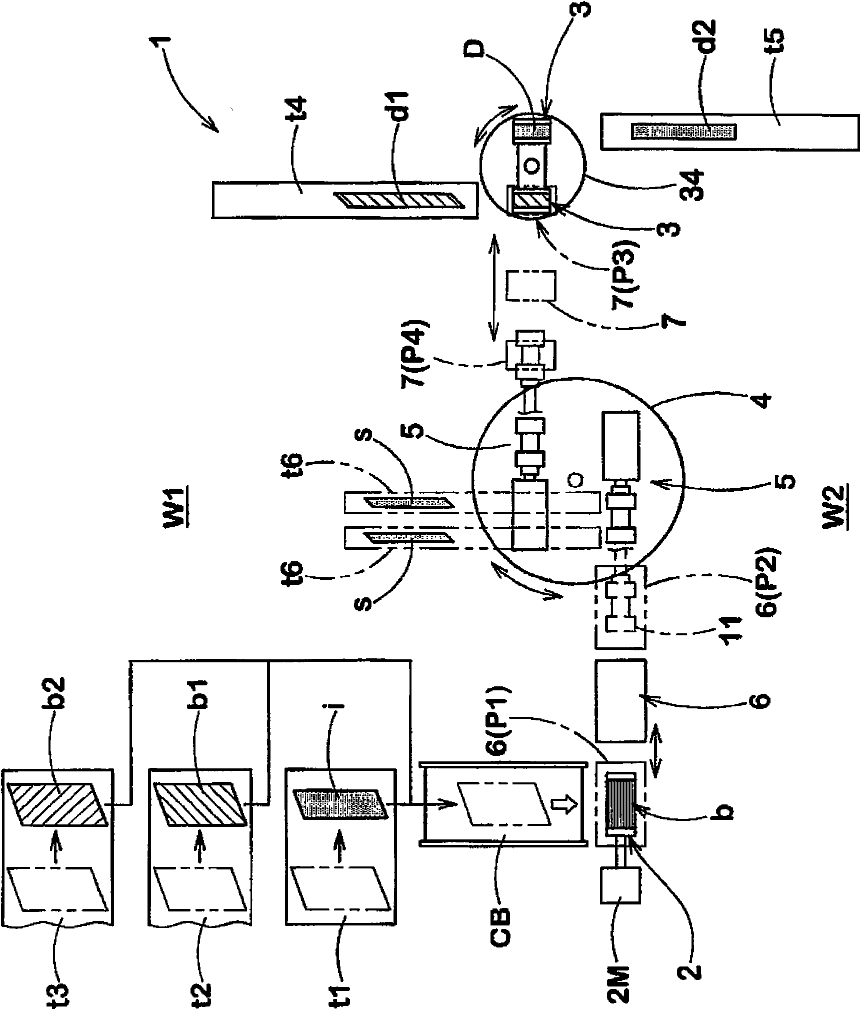
[0042] figure 1It is an overall plan view showing the green tire building apparatus 1 using the building machine of the present embodiment.

[0043] The structure of the raw tire building apparatus 1 of the present embodiment includes: a cylindrical first drum 2 for forming such as Figure 12 The green tire base B shown; the cylindrical second drum 3, which is used for forming such as Figure 14 The shown tread ring D; the turntable 4, which is provided rotatably about a vertical axis between the first drum 2 and the second drum 3; a pair of (ie, two) molding machines 5 provided on the turntable 4 ; the first conveying device 6, which is arranged between the above-mentioned first drum 2 and the building machine 5, and moves the green tire base B from the first drum 2 to the building machine 5; the second conveying device 7, which is arranged on the forming machine between ...


PUM


Abstract

The invention provides a simplified and minimized shaping former and a device for building green-tire including the same. The shaping former comprises bead-lock devices disposed side-by-side in the axial direction and supporting the green tire main body at the positions of the bead cores from the radially inside of the green tire main body; a rotation cylinder supporting the bead-lock devices capable of moving axially, and enabling the bead-lock devices to rotate together; a central shaft disposed in the tubular shaft and being rotatable independently of the tubular shaft; a motion converter converting rotational motion of the central shaft relative to the tubular shaft to linear motion for causing the bead-lock devices to come close to each other or to get away from each other; a single electric motor; and a clutch for switching transmission of the rotational motion of the single electric motor between a linear-motion mode and a rotational-motion mode, wherein the linear-motion mode is such that the output of the single electric motor is transmitted to only the central shaft, whereby the bead-lock devices come close to each other or get away from each other, and the rotational-motion mode is such that the rotational motion of the single electric motor is transmitted to both of the tubular shaft and central shaft so that the bead-lock devices rotate together, without causing the relative rotational motion.

Description

technical field [0001] The present invention relates to, for example, a building machine suitable for manufacturing radial tires and a raw tire building apparatus using the same. Background technique [0002] Conventionally, a two-stage molding method is known as a method of manufacturing a radial tire. In this two-step molding method, different devices are used for the first molding step and the second molding step. [0003] like Figure 14 As shown in (a) and (b) in chronological order, the first molding process winds the tire component b including the cord layer b1 on the cylindrical first molding drum A, and inserts the tire from the outside in the axial direction. A pair of bead cores c integrated with bead apex f to form a cylindrical raw tire base B. And, if Figure 14 (c), Figure 15 As shown, in the green tire base B, both end portions be of the cord layers protruding from the bead core c are folded back (folding step). [0004] Additionally, if Figure 16 As s...

Claims


Application Information

Patent Timeline
Patent Type & Authority Applications(China)
IPC IPC(8): B29D30/08B29D30/20B29D30/26
CPCB29D30/36B29D30/20B29D30/247B29D2030/206
Inventor 鬼松博幸
Owner SUMITOMO RUBBER IND LTD
Why Eureka
Try Eureka