Substrate floating device

A technology of substrates and buffer tanks, which is applied in the directions of measuring devices, manual conveying devices, transportation and packaging, etc. It can solve problems such as increased pressure loss, complicated piping operations, and constant floating pressure of unfloatable plates, so as to prevent pressure poor effect of loss

Inactive Publication Date: 2010-02-10
OLYMPUS CORP
View PDF1 Cites 6 Cited by
  • Summary
  • Abstract
  • Description
  • Claims
  • Application Information

AI Technical Summary

Problems solved by technology

That is, since the slack in the air piping increases by 200 mm from the farthest floating plate, it is necessary to guide the slack and elongated air piping, and there is a problem that the piping work is complicated
[0009] When the slack air pipe is rolled up on the side of the buffer tank, resistance to the flow of air is generated in the rolled up portion, so the pressure of the air flowing through each air pipe is different, and it is impossible to make each float The new problem of constant buoyancy pressure of the lifting board
[0010] In addition, since the length of all the air piping must correspond to the length of the air piping with the largest distance from the buffer tank to the floating plate, the pressure loss increases, and it is necessary to increase the pressure of the air supplied to the floating plate.

Method used


Image

  • Substrate floating device
  • Substrate floating device
  • Substrate floating device

Examples


Embodiment Construction

[0019] Below, while referring to the attached Figure 1 Next, a substrate floating device according to an embodiment of the present invention will be described.

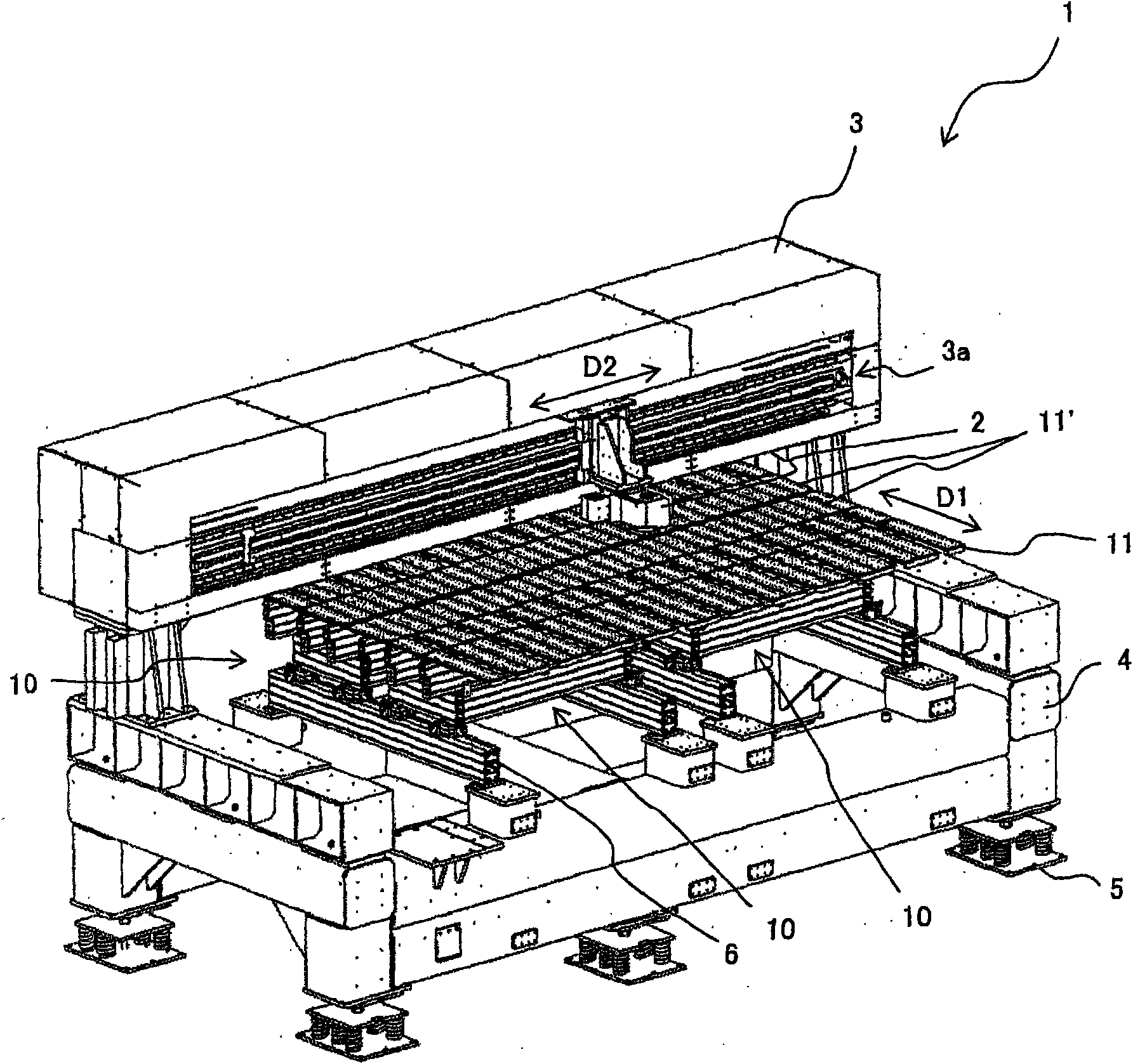
[0020] figure 1 It is a perspective view showing a substrate inspection device 1 including a substrate floating device 10 according to an embodiment of the present invention. In addition, in this figure, the illustration of the substrate conveying device for carrying in and carrying out the substrate and the slider for holding and conveying one side end of the substrate floated on the floating plate 11 is omitted. The substrate floating device 10 is arranged in the inspection area of ​​the substrate inspection device 1 , and the substrate carrying devices for carrying in and carrying out the substrate are arranged before and after the substrate carrying device 10 in the substrate carrying direction (arrow D1 ).

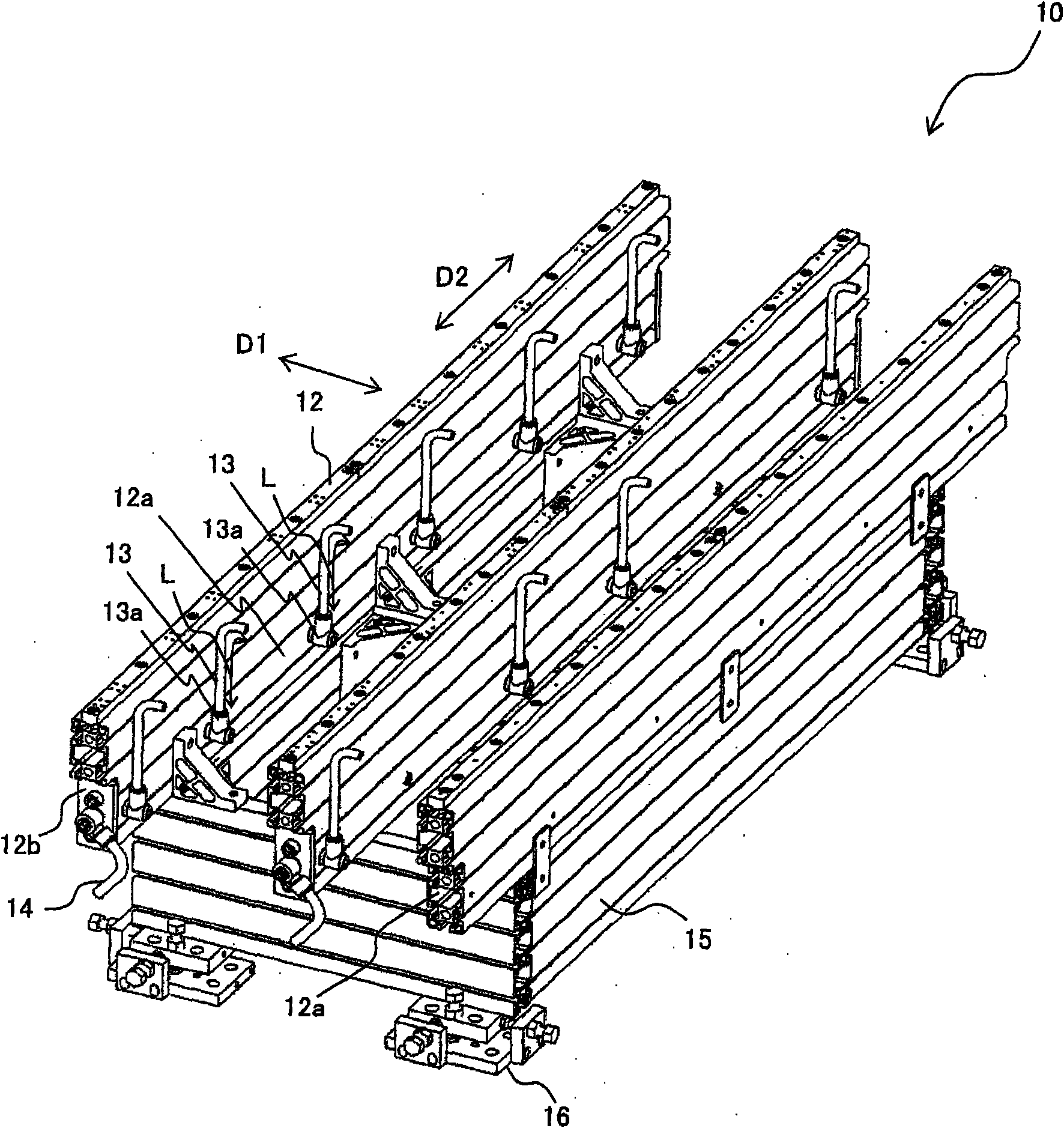
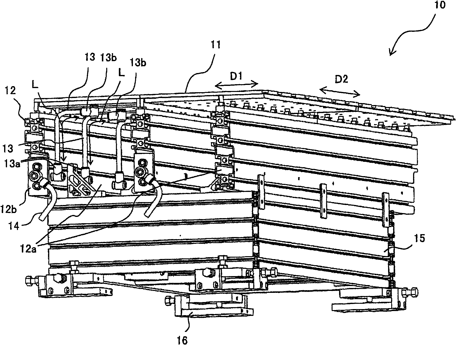
[0021] figure 2 is a perspective view of the substrate lifting device 10 viewed from above, image 3...


PUM


Abstract

The present invention provides a substrate floating device. In the substrate floating device, the air with constant pressure is supplied to a floating plate with a simple structure. The substrate floating device (10) comprises the following components: a plurality of floating plates (11) which discharge the air used for floating the substrate; a buffer tank (12a) which temporarily stores the air supplied by the plurality of floating plates (11); and a plurality of air tubes (13) which respectively supply air for the plurality of floating plates (11) from the buffer tank (12a), wherein, the floating plates (11) are of rectangular tile shaped and are arranged with a matrix shape. The buffer tank (12a) is configured below the area used for configuring the plurality of floating plates (11), and extends along one direction in the arrangement directions (arrows D1 and D2) of the floating plates (11). The plurality of air tubes (13) connect the buffer tank (12a) with the plurality of floating plates (11) with a substantially same length.

Description

technical field [0001] The present invention relates to a substrate floating device for floating a substrate such as a liquid crystal display (LCD) or another flat panel display (FPD) with air. Background technique [0002] Conventionally, in the process of forming a photoresist pattern on a glass substrate (plain glass) through a photolithography process to manufacture a liquid crystal panel and the inspection process of inspecting the glass substrate, the following method is used: the plain glass substrate is made of air. The plain glass substrate in the non-contact state is lifted and inspected or transported (for example, refer to Patent Document 1). [0003] In the case of using air to float the plain glass substrate, a plurality of glass substrates formed with air discharge holes are arranged side by side on the upper surface of the table on which the glass substrate is placed or the conveying surface on which the glass substrate is conveyed in the substrate inspection...

Claims


Application Information

Patent Timeline
Patent Type & Authority Applications(China)
IPC IPC(8): B65G49/06G02F1/13H01L21/677
CPCB65G7/06G01B21/00G02F1/13H01L21/683
Inventor 木内智一
Owner OLYMPUS CORP
Why Eureka
Try Eureka