Water stopping device for tunneling machine going in and out of tunnel and water stopping method

A water stop device, technology for entering and exiting holes

Active Publication Date: 2010-02-10
SHANGHAI CONSTRUCTION GROUP
View PDF1 Cites 14 Cited by
  • Summary
  • Abstract
  • Description
  • Claims
  • Application Information

AI Technical Summary

Problems solved by technology

[0006] 1. The existing water stop device is not applicable without auxiliary measures such as foundation reinforcement
[0007] 2. Even if the existing water stop device adopts auxiliary measures such as foundation reinforcement and precipitation, the effect is not ideal under extremely unfavorable geological conditions, such as high pressure water and weak foundation
[0008] 3. The setting of the water stop device is different when leaving the originating well and entering the receiving well, and the device cannot be reused
[0009] 4. When entering the receiving shaft, since the rubber cord is in the same direction as the machine tool, the safety factor is low
When the secondary hole technology is used, the risk is uncontrollable and the construction period is wasted during the period after the machine tool exits the hole door and before the steel plate is welded and sealed.
[0010] 5. The existing water stop device needs to be plugged when leaking, and the setting is to seal with welded steel plate, which is high risk and inconvenient

Method used


Image

  • Water stopping device for tunneling machine going in and out of tunnel and water stopping method
  • Water stopping device for tunneling machine going in and out of tunnel and water stopping method
  • Water stopping device for tunneling machine going in and out of tunnel and water stopping method

Examples


Embodiment 2

[0082] The difference between this embodiment and embodiment 1 is:

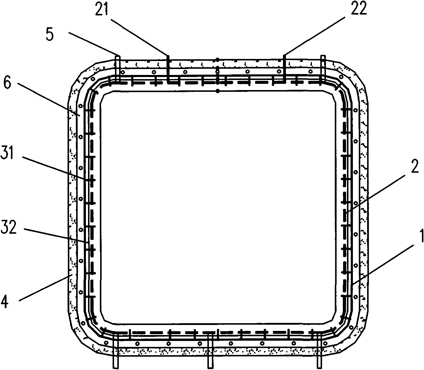
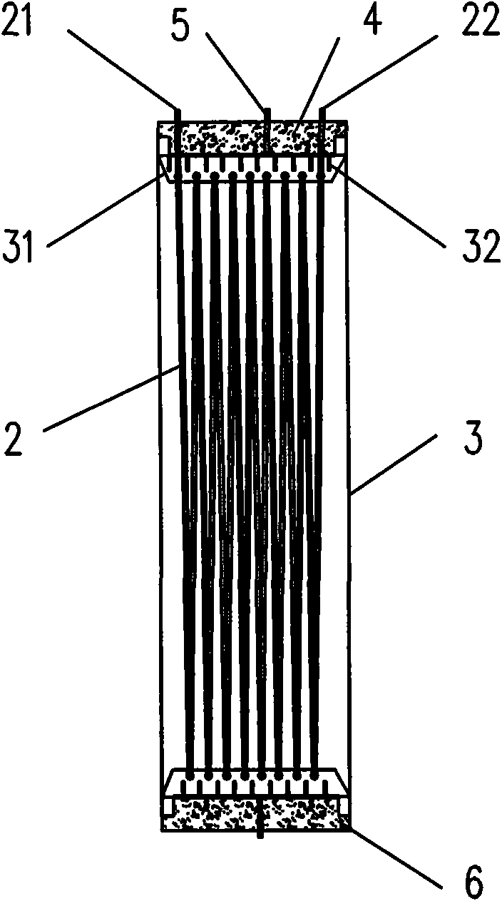
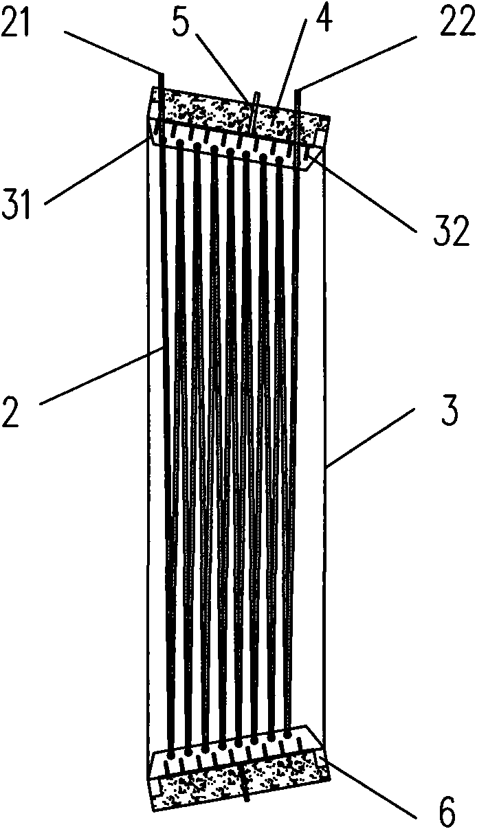
[0083] See image 3 with Figure 4 :The freezing pipe 2 is a pipe arranged in a serpentine shape, such as Figure 5 Shown is an expanded view of a serpentine arrangement of freezing tubes 2. The specific structure is as follows: The freezing pipe is a number of pipes evenly distributed on the inner wall of the sleeve. The head and tail of the pipe are placed in the longitudinal direction of the sleeve, and the adjacent pipes are connected by hoses in turn, thereby forming what is generally called Serpentine pipe. The inner wall of the sleeve 1 is staggered with several transverse stiffeners 31 and several longitudinal stiffeners 32. The transverse stiffeners 31 and the longitudinal stiffeners 32 are welded together. The transverse stiffeners 31 are provided with several small holes, which are frozen. The pipe 2 passes through the small hole, thereby forming a serpentine pipe. In addition, the cross section of...


PUM


Abstract

The invention relates to the field of building construction, in particular to a water stopping device for a tunneling machine going in and out of a tunnel and a water stopping method. The water stopping device for the tunneling machine going in and out of the tunnel comprises at least one water stopping casing box with openings at the front part and the back part. The water stopping casing box isarranged at the periphery of a doorway part which is in an enclosure protection structure, is fixedly connected with the enclosure protection structure in a sealing way, and comprises a sleeve with openings at the front part and the back part and a freezing pipe. The freezing pipe is arranged on the inner wall of the sleeve, and is used for injecting refrigerant. A grouting pipe which is communicated with the inner cavity of the sleeve is arranged on the sleeve. The invention also discloses the water stopping method adopting the water stopping device. The freezing pipe can change mixed paste between the water stopping casing box and the tunneling machine or a pipeline into a freezing body. The freezing body can block off a leakage path, ensure that groundwater which possibly leaks can be frozen in time when the tunneling machine or the pipeline structure moves relative to the water stopping casing box, thereby achieving the purpose of water stopping.

Description

Technical field [0001] The invention relates to the field of building construction, in particular to a water-stop device and a water-stop method for tunneling machines and tools. Background technique [0002] The existing pipe jacking and tunnel construction have two key processes: exiting the launch well and entering the receiving well. These two key processes are related to the setting of the water stop system. [0003] When exiting the launch well, the water stop device of the pipe jacking and shield tunnel generally adopts systems such as rubber cord sock, one-way hinge plate and rubber cord. The rubber cord sock system is not equipped with one-way hinge plates, and is used in pipeline construction with better geological conditions and smaller diameters. In the one-way hinged plate and rubber cord system, the rubber cord is supported by the one-way hinged plate, which is used in the construction of pipelines with poor geological conditions and large diameters. According to t...

Claims


Application Information

Patent Timeline
Patent Type & Authority Applications(China)
IPC IPC(8): E21D11/38
Inventor 胡玉银杨子松佘清雅颜正红
Owner SHANGHAI CONSTRUCTION GROUP
Why Eureka
Try Eureka