Central tube type composite optical cable
A technology of composite optical cable and central bundle tube, which is applied in the direction of fiber mechanical structure, etc., can solve the problems of small communication capacity, poor pressure resistance performance and fiber breakage of optical cable, and achieve the effect of reducing requirements, good pressure resistance performance and cost saving
- Summary
- Abstract
- Description
- Claims
- Application Information
AI Technical Summary
Problems solved by technology
Method used
Image
Examples
Embodiment 1
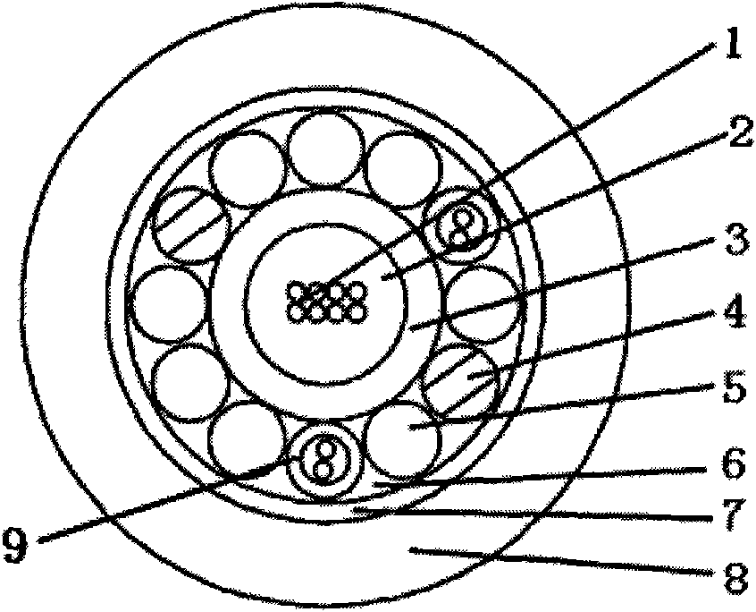
[0021] please see figure 1 , a central beam tube type optical cable composite optical cable, which includes a circular central beam tube 3, which contains an optical fiber 1 and an internal water blocking object 2, along the outer wall of the central beam tube with the axis of the central beam tube as the center, extending longitudinally and The reinforcing member 4 is covered with a unidirectional spiral or a clockwise / counterclockwise alternate direction spiral, the reinforcing member 4 is provided with a protective layer 7, and there is an external water blocking object 6 in the gap between the protective layer 7 and the central bundle tube , the protective layer 7 is provided with a sheath layer 8; it is characterized in that: the reinforcing member 4 contains at least two optical or electrical conduction units 9, and the reinforcing member 4 also includes fillers 5, which are symmetrically distributed in the center Outside the bundle tube, the pitch of the helix is 300m...
Embodiment 2
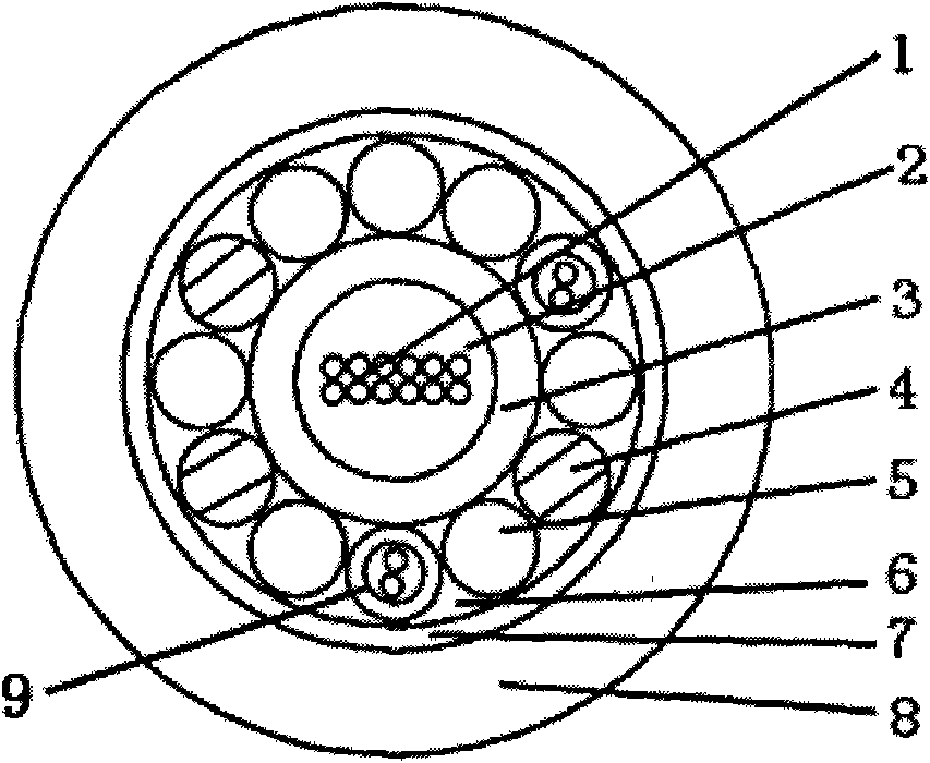
[0023] please see figure 2 , which is basically the same as that of Example 1, except that the number of optical fibers is changed from 8 to 12, and one filler is replaced by a reinforcement; the filler is asymmetrically distributed outside the central beam tube.
Embodiment 3
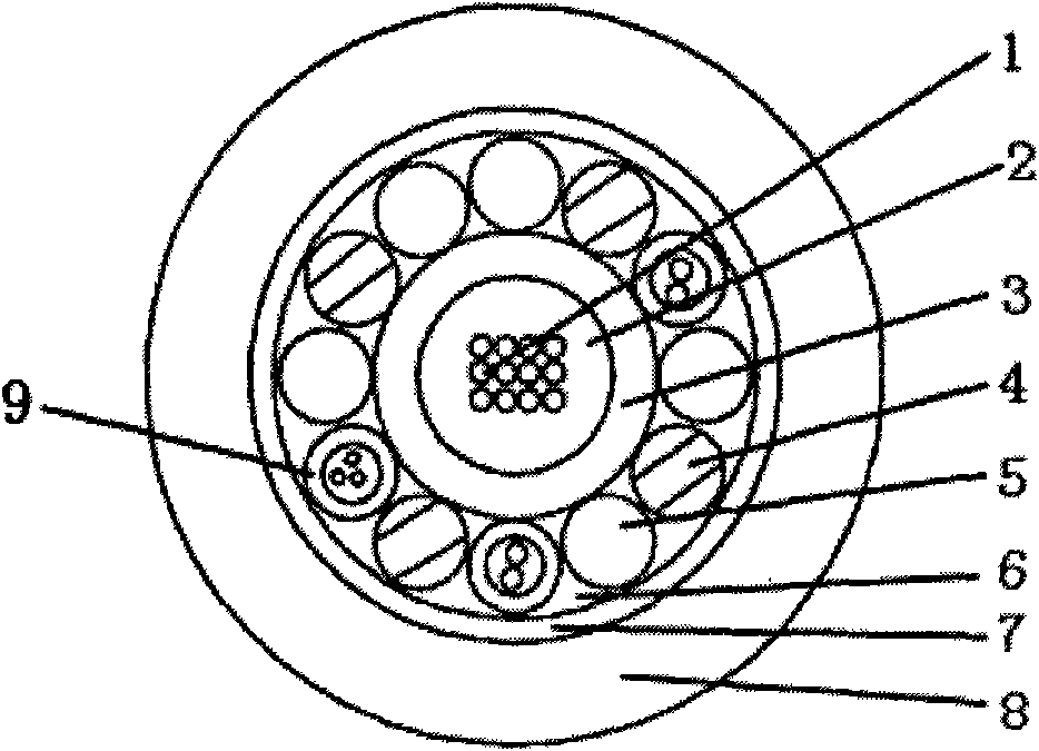
[0025] please see image 3 , basically the same as the implementation example 2, the difference is that: the number of optical fibers has changed from two 6-core fiber ribbons to three 4-core fiber ribbons; one of the strengthening members is replaced by an optical or electrical conduction unit; and there are 2 other The root fillers are replaced by reinforcements, the reinforcements are symmetrically distributed outside the central bundle tube, and the fillers and reinforcements are asymmetrically distributed outside the central bundle tube.
[0026] In the present invention, since the reinforcing member is in direct contact with the central bundle tube and tightly wrapped on the central bundle tube in a spiral manner, it effectively prevents the shrinkage of the central bundle tube when the temperature cycle changes, so that the optical fibers in the splice box will not be affected by temperature. Changes and easy to break; in addition, because non-metallic fillers are inclu...
PUM
 Abstract
Description
Claims
Application Information
 - R&D
- Intellectual Property
- Life Sciences
- Materials
- Tech Scout
- Unparalleled Data Quality
- Higher Quality Content
- 60% Fewer Hallucinations
Browse by: Latest US Patents, China's latest patents, Technical Efficacy Thesaurus, Application Domain, Technology Topic, Popular Technical Reports.
© 2025 PatSnap. All rights reserved.Legal|Privacy policy|Modern Slavery Act Transparency Statement|Sitemap|About US| Contact US: help@patsnap.com


