Method for removing support positioning structure of irradiation monitoring pipe

A technology for irradiating supervision tubes and supporting positioning, which is applied in the directions of reactor fuel elements, reactors, and greenhouse gas reduction. It can solve problems such as lack of fixation of sample tubes, rupture of sample tubes, and threats to safe operation, so as to reduce foreign objects falling into refueling. Risks of pools, control of usage costs, effects of reducing radiation doses

Active Publication Date: 2010-02-10
QINSHAN NUCLEAR POWER
View PDF0 Cites 3 Cited by
  • Summary
  • Abstract
  • Description
  • Claims
  • Application Information

AI Technical Summary

Problems solved by technology

[0003] After the supporting springs and supporting ribs in the supporting and positioning structure of the irradiation supervision tube are broken, the sample tube is not fixed, and the sample tube will break or break under the impact of vibration and water flow, losing its supervision significance
And the broken support ribs and springs will become metal foreign objects inside the pressure vessel, which will cause damage to the fuel assembly and pressure vessel under the impact of water flow, threatening safe operation
If this defect is not eliminated, when the sample tube of the irradiation supervision tube breaks or other defects occur, the power plant will be shut down, and the loss and impact caused are immeasurable

Method used


Image

  • Method for removing support positioning structure of irradiation monitoring pipe
  • Method for removing support positioning structure of irradiation monitoring pipe

Examples


Embodiment Construction

[0019] The method for dismantling the supporting and positioning structure of the irradiation supervisory tube according to the present invention will be further described below in conjunction with the accompanying drawings and specific embodiments.

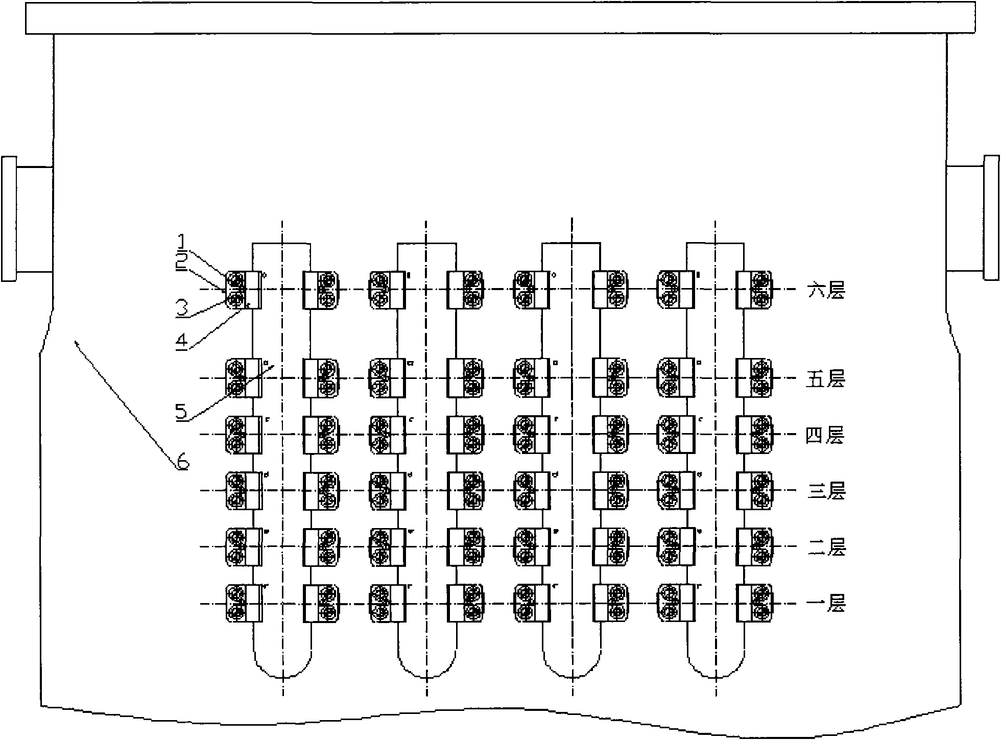
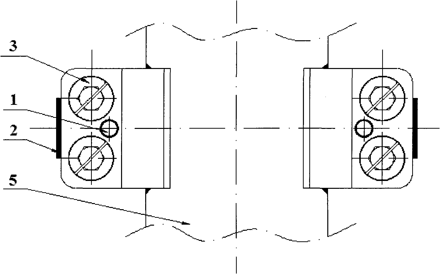
[0020] Such as figure 1 and figure 2 As shown, the support and positioning structure of the irradiation supervision tube is composed of eight sheath tubes 5, and each sheath tube has six layers of support brackets 4, which are positioned by positioning pins 1 and installed on the reactor pressure vessel hanging basket cylinder through bolts 3. , fixed on the outer wall 6 of the spider plant through the welds 2 on both sides of the support bracket.

[0021] The supporting positioning structure of the irradiation supervision tube is divided into two groups and fixed symmetrically on the outer wall of the hanging basket. After several operating cycles of irradiation, the dismantling of the supporting and positioning structure can...


PUM


Abstract

The invention provides a method for removing a support positioning structure of an irradiation monitoring pipe, comprising the following steps: (a) incising all the bolts on the support positioning structure of the irradiation monitoring pipe; (b) incising all the position pins on the support positioning structure of the irradiation monitoring pipe; (c) incising all the welding lines between the support brackets of the rest layers of the support positioning structure of the irritation monitoring pipe except the intermediate layer thereof and the hanging basket wall; (d) lifting the support positioning structure of the irritation monitoring pipe and incising the welding lines between the support bracket of the intermediate layer of the support positioning structure of the irritation monitoring pipe and the hanging basket wall to lead the support positioning structure of the irritation monitoring pipe to be disassembled into a plurality of support brackets; and (e) incising the obtainedmultiple support brackets by three sections, and placing into a lead shielding container after incising. The method in the invention can lead the incision trace of the hanging basket wall to be neat and smooth, thus facilitating mounting a new support positioning structure of the irritation monitoring pipe.

Description

technical field [0001] The invention relates to the maintenance technology of nuclear power plant equipment, in particular to a method for dismantling the support and positioning structure of the irradiation supervision tube of the pressurized water reactor nuclear power plant after irradiation. Background technique [0002] The irradiation monitoring tube is a device for monitoring the changes in the material properties of the reactor pressure vessel material after neutron irradiation. The tube is equipped with radiation tubes of the same material, furnace number and process as the base material and weld of the reactor pressure vessel cylinder. According to the supervisory tube sample, neutron flux measuring piece, temperature measuring alloy, etc., supporting ribs and supporting springs are arranged on the outer circle of the connecting pipe and the gripping head. [0003] After the supporting spring and supporting ribs in the supporting positioning structure of the irradi...

Claims


Application Information

Patent Timeline
Patent Type & Authority Applications(China)
IPC IPC(8): G21C19/26
CPCY02E30/30
Inventor 何小剑陈梁何少华戚宏昶王成林
Owner QINSHAN NUCLEAR POWER
Why Eureka
Try Eureka