Low-cross coupling groove array antenna

An array antenna and groove technology, which is applied to antennas, slot antennas, antenna coupling and other directions, can solve problems such as inaccessibility and complex production, and achieve the effect of reducing mutual coupling and improving radiation performance.

Inactive Publication Date: 2010-02-10
INST OF OPTICS & ELECTRONICS - CHINESE ACAD OF SCI
View PDF1 Cites 18 Cited by
  • Summary
  • Abstract
  • Description
  • Claims
  • Application Information

AI Technical Summary

Problems solved by technology

On page 308 of the book "Theory and analysis of phased array antennas, M.Amitay, V.Galindo and C.P.Wu, published by Wiley Interscience", it is introduced that a rectangular waveguide is loaded around the circular waveguide, so each circular waveguide and a rectangular waveguide An array unit is formed, where the rectangular waveguide acts as a choke slot, which can cut off the surface current propagating between the circular waveguides, but the production is more complicated
Later, in the patent "EP055

Method used


Image

  • Low-cross coupling groove array antenna
  • Low-cross coupling groove array antenna
  • Low-cross coupling groove array antenna

Examples


Embodiment 1

[0045] Embodiment 1 is a groove slot array antenna when the number of slot array units is 2

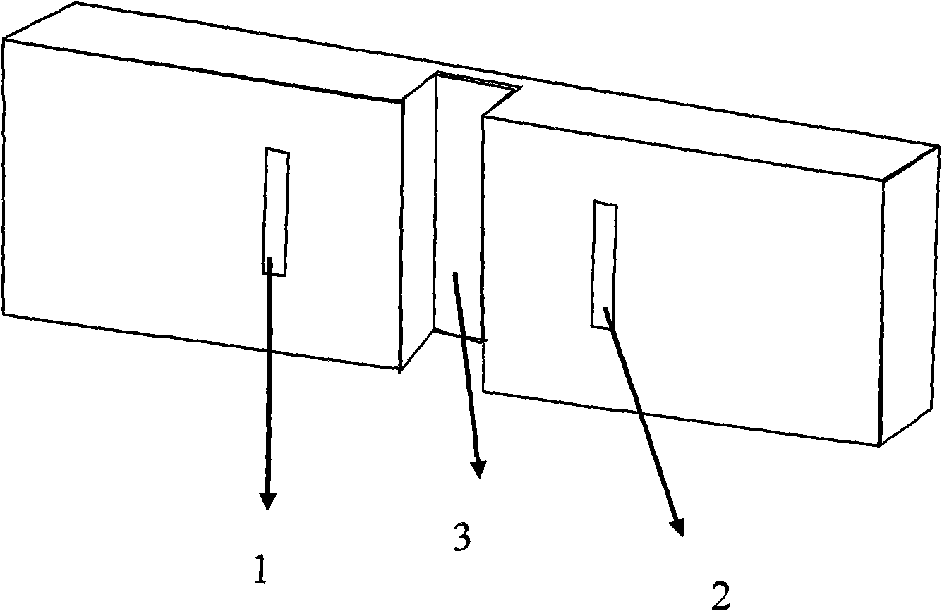
[0046] a) The working frequency of the array antenna is 14.5GHz, and the waveguide slot antenna unit is used, such as Figure 6 Mark 1 and 2, the number of array units is two. The gap parameter is 10.3mm×1.5mm;

[0047] b) The slot array units at the end of the waveguide are arranged in a rectangular grid, and the distance between the array units is 18mm;

[0048] c) A groove structure with a rectangular cross-section is symmetrically arranged at both ends of the array unit. The grooves at both ends of the array 1 are g1 and g2, and the grooves at both ends of the array 2 are g3 and g4. The grooves are air and not filled with medium. The parameters of the groove are as follows: width w=2.1mm, depth d=3.9mm, length Sw=30mm and the distance between the groove and the slot p=7mm, and finally the whole antenna size is 50mm×30mm×6mm.

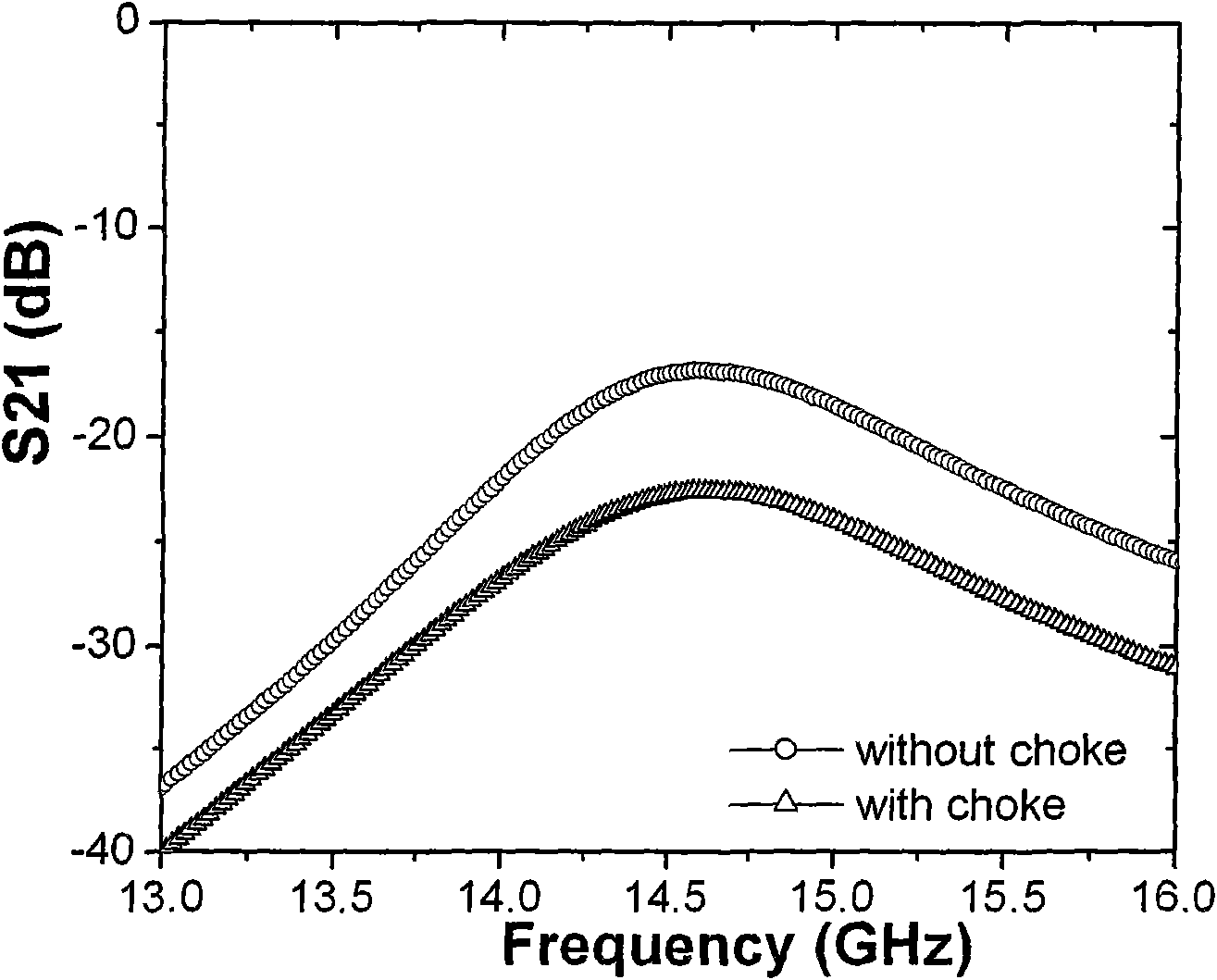
[0049] d) After the groove parameters are optimized...

Embodiment 2

[0056] Embodiment 2 is a groove slot array antenna when the number of slot array units is 4, such as Figure 13 shown.

[0057] a) The working frequency of the array antenna is 14.5GHz, and the waveguide slot antenna unit is used, such as Figure 13 Label 1, 2, 3 and 4, the number of array elements is four. The gap parameter is 10.3mm×1.5mm;

[0058] b) The slot array units at the end of the waveguide are arranged in a rectangular grid, and the distance between the array units is 18mm;

[0059] c) A trench structure with a rectangular cross section is arranged symmetrically at both ends of the array unit, and the trench is filled with air and not filled with a medium. The parameters of the groove are as follows: width w=1.8mm, depth d=4.1mm, length Sw=30mm and the distance p=7.5mm between the groove and the slit, as shown in Figure 11, the final size of the entire antenna is 80mm×30mm ×6mm.

[0060] d) After the groove parameters are optimized, the gap parameters are adju...

Embodiment 3

[0064] Embodiment 3 is the situation when the number of array elements is 2, and the grooves are not symmetrically distributed at both ends of the array elements, such as Figure 17 shown.

[0065] a) The working frequency of the array antenna is 14.5GHz, and the waveguide slot antenna unit is used, such as Figure 17 Mark 1 and 2, the number of array units is two. The gap parameter is 10.3mm×1.5mm;

[0066] b) The slot array units at the end of the waveguide are arranged in a rectangular grid, and the distance between the array units is 18mm;

[0067] c) A groove structure with a rectangular cross-section is arranged at both ends of the array unit (at this time, the grooves are not symmetrically distributed at both ends of the array element), and the groove is filled with air and not filled with a medium. The parameters of the groove are as follows: width w=2.7mm, depth d=3.7mm, length Sw=30mm and the distance between the groove and the slit are respectively p1=8mm and p2=...


PUM


Abstract

The invention relates to a low-cross coupling groove array antenna which has the basic principle that a pair of surface groove structures is symmetrically loaded at both sides of adjacent array unitsto modulate the surface wave propagation, and the distribution of surface electromagnetic energy is changed, thereby enabling the energy disturbance among array elements to be quickly reduced. In addition, partial surface electromagnetic energy is radiated to free space with the dispersion of an SPs groove structure, thus increasing the antenna gain, and compressing the wave beam width of the antenna, and therefore, the radiation performance of the antenna is obviously improved. Compared with a structure traditionally restraining surface wave, the novel groove wave-guide gap SP antenna has simple structure and low cost, and the radiation performance such as antenna gain and the like is increased when the surface wave is restrained at the same time. The invention can be widely applied to linear array antenna, area array antenna, phased array antenna and the like.

Description

technical field [0001] The invention relates to an array antenna, in particular to a slot array antenna with low mutual coupling. Background technique [0002] In modern radar and communication systems, the array antenna is a commonly used antenna form. It is a directional antenna composed of many radiating elements arranged. In the phased array antenna, the amplitude excitation and phase of each element can be controlled. of. However, the mutual coupling between the antenna radiation elements due to the mutual crosstalk of surface waves will have an important impact on the performance of the array antenna, resulting in the distortion of the radiation pattern of the array elements, resulting in a decrease in beam control accuracy, and even causing scanning blind spots, reducing the Scanning capabilities of small phased array antennas. Therefore, how to suppress the mutual coupling between array antenna elements has become a hot spot for researchers. [0003] In recent yea...

Claims


Application Information

Patent Timeline
IPC IPC(8): H01Q13/08H01Q13/10H01Q21/00H01Q1/52
Inventor 赵泽宇黄成冯沁崔建华罗先刚
Owner INST OF OPTICS & ELECTRONICS - CHINESE ACAD OF SCI
Why Eureka
Try Eureka